15
2. Mark center point where the chimney goes through the ceiling and roof.
3. On same center outline square X = 12” x 12” (305mm x 305mm) – USA, or 14” x 14” (355mm x 355mm) – Canada
framing opening as required by approved chimney support. Check to make sure no roof joist is in the way. Should
there be one, move Heater to the left or right so that it lines up with the newly located center point/frame opening.
Maintain vapor barrier.
TYPICAL FRAMING DIMENSIONS
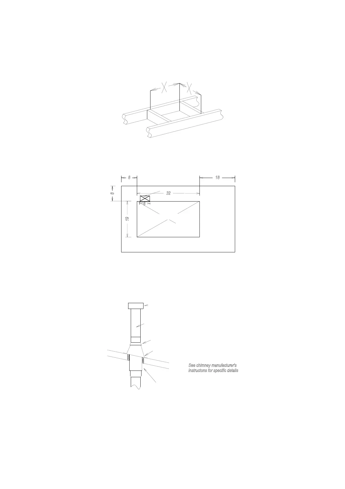
4. Mark outline to the outside air duct on floor again, making sure no joist has to be cut. Frame opening and maintain
vapor barrier. Duct framing dimensions are 3-1/2” x 6” (89 x 152mm).
3.5
NCM120E
Stove Board
Air duct location
ins
mm
450200
485
150
90
810
cut out
200
LOCATION AND DIMENSIONS OF AIR INTAKE
DUCT HOLE AND FLOOR PROTECTOR AS SEEN FROM TOP
5. Remove the heater, cut the holes and prepare framing. Restore the integrity of the vapor barrier with suitable tape
and/or caulking.
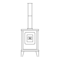
6. Install chimney ceiling support box JSC6CCSB (USA) or JM6CCS (Canada). Slide into opening level and nail
through box framing using four 2” spiral nails or equivalent per side.
Rain Cap
Chimney section
Storm collar
Roof flashing
Ceiling Support Box
Overlap roof shingle
Spark Arrestor
TYPICAL CEILING SUPPORT BOX INSTALLATION
7. Prepare floor protector. Locate onto floor and cut 3-1/2” x 6” (89 x 152mm) hole.
8. Position floor protector and install outside air duct through floor.