EasyManuals Logo

Newport Electronics i Series User Manual

Newport Electronics i Series
69 pages
To Next Page IconTo Next Page
To Previous Page IconTo Previous Page
Page #15 background imageLoading...
Page #15 background image
11
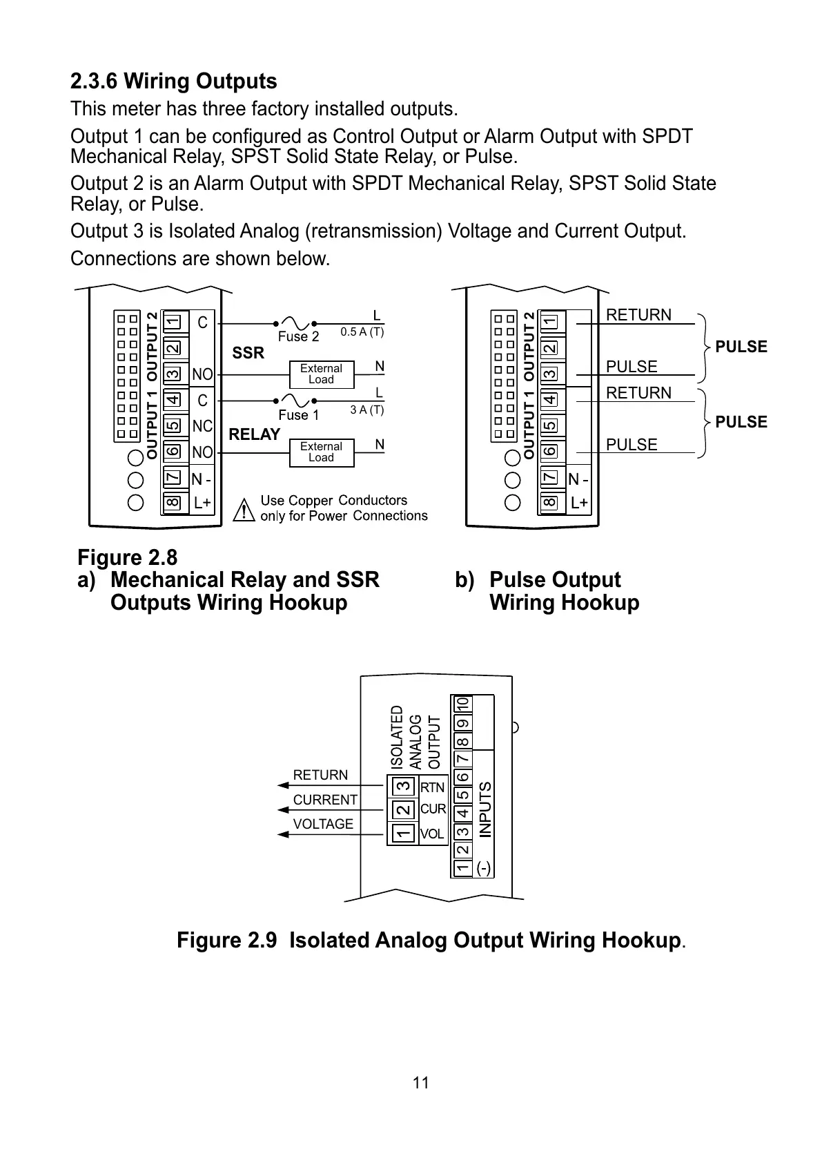
2.3.6 Wiring Outputs
This meter has three factory installed outputs.
Output 1 can be configured as Control Output or Alarm Output with SPDT
Mechanical Relay, SPST Solid State Relay, or Pulse.
Output 2 is an Alarm Output with SPDT Mechanical Relay, SPST Solid State
Relay, or Pulse.
Output 3 is Isolated Analog (retransmission) Voltage and Current Output.
Connections are shown below.
Figure 2.8
a) Mechanical Relay and SSR b) Pulse Output
Outputs Wiring Hookup Wiring Hookup
Figure 2.9 Isolated Analog Output Wiring Hookup
.
123456789
10
RETURN
CURRENT
VOLTAGE
SSR
RELAY
External
Load
External
Load
0.5 A (T)
3 A (T)
C
NO
C
NC
NO
OUTPUT 1 OUTPUT 2
OUTPUT 1 OUTPUT 2
RETURN
PULSE
RETURN
PULSE
PULSE
PULSE
All manuals and user guides at all-guides.com

Table of Contents

Questions and Answers:

Question and Answer IconNeed help?

Do you have a question about the Newport Electronics i Series and is the answer not in the manual?

Newport Electronics i Series Specifications

General IconGeneral
BrandNewport Electronics
Modeli Series
CategoryMeasuring Instruments
LanguageEnglish

Related product manuals