Do you have a question about the Newport Electronics INFCP-B Series and is the answer not in the manual?
Outlines the purpose of the manual in guiding users through setup and operation.
Details essential steps for setting up and operating the programmable digital meter.
Covers advanced or supplementary configuration and operational settings.
Instructions for verifying received equipment and checking for shipping damage.
Critical safety guidelines and warnings for installation and operation of the meter.
Overview of the Digital Programmable Process meter's capabilities and functions.
Lists the standard and optional features of the INFINITY® C Process Panel Meter.
Details optional accessories that can enhance or complement the meter's functionality.
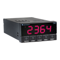
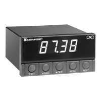
Describes the physical layout and components of the meter's front panel.
Explains the connectors and labels located on the rear of the meter.
Provides steps for safely opening the meter for internal access or adjustments.
Location and description of the meter's rating and product identification label.
Guidance on configuring power settings using jumpers on the main board.
Step-by-step instructions for physically installing the meter into a panel.
Detailed diagrams and instructions for wiring various sensor inputs to the meter.
Procedures for connecting AC and DC main power to the meter.
Instructions for wiring an external switch for the tare function.
Guides for connecting analog output and relay output options.
Procedure for configuring the meter to accept different types of input signals.
Steps to set the desired decimal point location for the display.
Methods for scaling meter readings to engineering units using known or unknown inputs.
Configuration options for tare, input resolution, and filtered/unfiltered signal display.
Instructions for changing the display color, applicable to Version 'B' meters.
Configuration options for setpoint 1, including active band and latching behavior.
Configuration options for setpoint 2, including active band and latching behavior.
Procedure to adjust the hysteresis (deadband) for Setpoint 1.
Procedure to adjust the hysteresis (deadband) for Setpoint 2.
Configuring analog output settings, including type, scaling, and proportional control.
Setting the proportional band for proportional control analog output.
Adjusting the manual reset feature to offset errors relative to setpoints.
Scaling analog output signals to match display readings or engineering units.
Configuring lock-out features for the RESET button, setpoint changes, and firmware version display.
Adjusting the display brightness level, applicable to Version 'B' meters.
Details input ranges, isolation, noise rejection, and resistance characteristics.
Information on the specifications for the dual Form 'C' on/off alarm relays.
Specifications for the analog output signal type, level, function, and linearity.
Specifications for isolated analog output, similar to non-isolated but with isolation.
Details AC and DC input power requirements and consumption.
Operating and storage temperature ranges, and relative humidity limits.
Specifications for panel cutout dimensions, weight, case material, and protection.
Safety requirements for electrical equipment for measurement, control, and laboratory use.
Immunity and emissions requirements for electrical equipment in measurement and laboratory settings.
Procedure for obtaining authorization and submitting products for warranty or repair.
| Brand | Newport Electronics |
|---|---|
| Model | INFCP-B Series |
| Category | Measuring Instruments |
| Language | English |