3
Getting Started
14
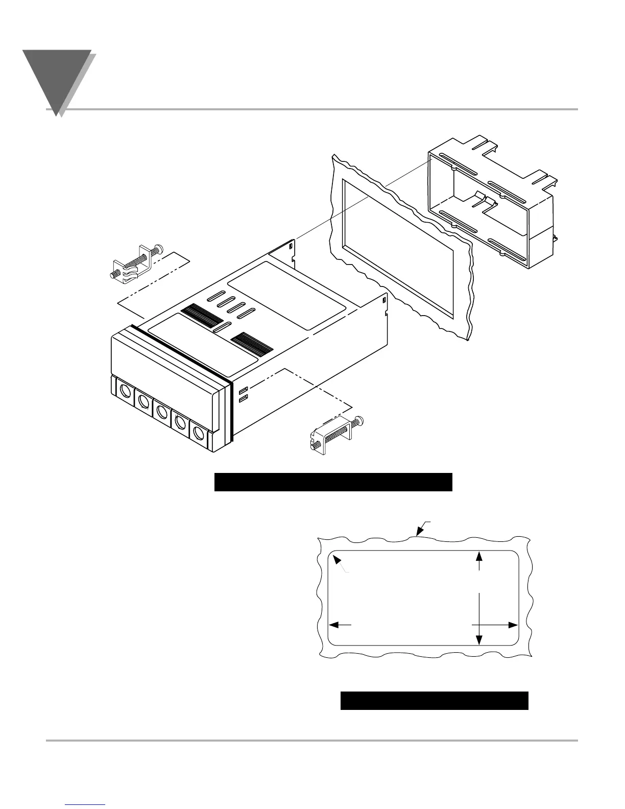
3.3 PANEL MOUNTING
Figure 3-4. Meter - Exploded View
1. Cut a hole in your panel, as
shown in Figure 3-4. For
specific dimensions refer to
Figure 3-5.
2. Insert the meter into the hole.
Be sure the front bezel gasket
is flush to the panel.
3. Slide on mounting bracket to
secure.
4. Proceed to Section 3.4 to
connect your sensor input and
main power.
Figure 3-5. Panel Cut-Out
 Loading...