Do you have a question about the Next Wave CNC SHARK and is the answer not in the manual?
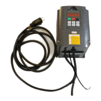
Lists components provided by Next Wave for the spindle VFD setup.
Details required tools and parts to be provided by the user for setup.
Unplugging the VFD power supply and removing the front cover.
Moving the internal jumper to the VI (left) position for speed control.
Loosening specific terminals (DCM, ACM, RS-, RS+) for wiring.
Guiding the speed control cable through the VFD's bottom grommet.
Connecting jumper wire, green, black, and red wires to designated terminals.
Using a zip tie to bundle the spindle cable and trimming excess.
Securing the VFD's front panel after internal wiring is completed.
Plugging the VFD power cord into a 110V outlet and observing the display.
Accessing program parameters (e.g., Pdxxx) using the PRGM button.
Setting the program registry number to Pd001 and accessing its configuration window.
Adjusting the setting for Pd001 to '2' and saving the configuration.
Repeating the setup process for other listed registry numbers and using programming tips.
Unplugging the VFD and connecting the interface cable to the control box port.
Updating software, setting RPM, and performing the correct power-on sequence for synchronization.
Guidance for VFD/Control Box sync issues and contact information for assistance.
This document outlines the setup procedure for the Shark CNC Spindle VFD (inverter) to enable the use of a Spindle Speed Interface cable, allowing for automated spindle speed control. The process involves both hardware modifications to the VFD and software updates for the CNC control box and post-processor.
The Shark CNC Spindle VFD (Variable Frequency Drive), also known as an inverter, is a crucial component that controls the speed of the CNC spindle motor. By integrating the Spindle Speed Interface cable, the VFD can receive speed commands directly from the CNC control box, enabling automated RPM adjustments based on the toolpath settings defined in CAM software like VCarve or Aspire. This eliminates the need for manual speed adjustments on the VFD, streamlining the machining process and improving precision. The system is designed to ensure that RPM settings from the CAM software are accurately translated to the spindle, enhancing the overall efficiency and reliability of the CNC operation.
The VFD operates on a 110V power supply and is rated for 1.5KW, as indicated by the "110V 1.5KW" label on the unit. The setup requires specific electrical connections within the VFD's terminal block, including DCM, ACM, RS-, and RS+ terminals, which are used for the speed control interface. A jumper wire (1 to 1.5" long, braided or solid 18 or 20-gauge) is needed to connect DCM and ACM. The Spindle Speed Interface cable itself connects to the VFD and then to the control box, transmitting the necessary signals for speed control.
The system relies on specific firmware and software versions for proper functionality:
The VFD's display shows various parameters, including "Pdxxx" for program registry numbers and "Hz," "RPM," and other views for operational status. The setup involves modifying several program registry settings (e.g., PD001, PD002, PD004, PD005, PD008, PD009, PD010, PD011, PD014, PD015, PD070, PD072, PD141, PD142, PD143, PD144, PD163, PD164, PD165) to configure the VFD for external speed control.
Once set up, the system offers several key usage features:
The setup and ongoing maintenance involve several steps to ensure proper functionality:
The system is designed for "World Class. Made in USA." quality, emphasizing reliability and performance for CNC applications.
| Brand | Next Wave CNC |
|---|---|
| Model | SHARK |
| Category | Inverter |
| Language | English |