MASTERTRACE
4.1
Chapter 4 Installation
4 Installation
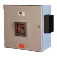
4.1 Control Panel Mounting
Mount the control panel at a convenient location, gener-
ally with the Interface Module at eye level. Placing the
Interface Module in direct sunlight may make reading the
display difficult.
Cut holes and mount hubs at suitable locations in the
enclosure as required. It is recommended that power
wires are run in separate conduits from RTD and RS-485
signal wires.
4.2 RTD Sensor Wiring
RTD Sensors should be 3-wire, 100 W, platinum to DIN
standard 43760. Mount the RTD element on the pipe,
away from the heat trace and 30° to 45° from the bottom
of the pipe. The total circuit resistance per conductor
from the RTD to the control panel must be less than 10
ohm. Exceeding this resistance will result in non-linear
temperature measurement. Beldon cable 8770 or
equivalent will allow RTDs to be placed up to 1,000 feet
from the control panel. Complete all RTD wiring
according to the Panel Layout Drawings located in the
control panel package.
The RTD sensor must be installed on the pipe surface or
thermal well before the pipe insulation to ensure proper
thermal contact. The RTD position should be 180° from
the electric heat trace cable which is the coldest spot of
the pipe. The RTD sensor may be secured to the pipe by
fiber-glass tape. The RTD probe is delicate and should
not be bent or used as a tool to puncture insulation. If
additional wiring is required for the RTD, shielded 3-lead
wire sized 18 or 20AWG must be used for the RTD
sensor to minimize the effects of noise pickup. A typical
RTD installation is shown in Figure 4.1.
Figure 4.1 RTD Mounting
4.3 Ground Fault Protection
In order for the ground fault protection to be effective, a
solid ground path must be provided for the heat trace.
Electrical heat trace with a grounded outer braid or
conductive sheath is recommended. For ground fault
monitoring, each heater circuit ground must be individu-
ally returned. Ground fautl protection is for equipment
protection only, not personnel.
4.4 Ground Fault Testing
To test the ground fault monitoring function on 5 and 10
point modules, a ground fault test function is available. A
90mA ac current source is provided on terminals 120 and
121 where a wire loop is inserted through all ground CTs
and terminated at the GF test terminals. The GF test wire
loop is internally wired on internal mechanical switch
models. See Typical Wiring Diagram in Appednix D for
details.
4.5 Power and Heater Wiring
Complete all supply and load wiring for the heater circuits
according to the Typical Wiring Diagram. Note that
voltages may vary by circuit. Power wiring should be
sized appropriately to the breaker size and maximum
ambient operating temperatures. Control panels with
breakers built-in will require a power feed size appropri-
ately to the main breaker size.
Wiring methods should comply with
Canadian Electrical or National Electrical
Code and local codes. Power and signal
wires should not be run in the same conduit
system. Wiring should be rated at least 90
°C. Wiring methods must conform to Class
1, Div.2 or Class 1, Zone 2 requirements.
4.6 Ground Connection
A dedicated ground wire must be connected to the ground
lug or bar on the control panel. This provides a solid
ground path in the event of a fault. The input transient
Wire Size (AWG) Current Load (A)
Max. Ambient
Temperature (°C)
6 30 50
8 30 40
10 24 50
12 16 50