MASTERTRACE
1.1
Chapter 1 Overview
1 Overview
1.1 Use of This Manual
Reading a lengthy instruction manual on a new product is
not a task most people enjoy. To speed things up,
Chapter 2, Getting Started, provides a step-by-step
tutorial for a heat trace application. Chapter 4, Installa-
tion, discusses important mounting and wiring issues for
reliable operation. Detailed information relating to switch
and output ratings, accuracy and so forth are detailed in
Section 3.3, Specification. The remainder of this manual
should be read and kept for reference to provide the
maximum benefit of the MasterTrace Controls.
1.2 Related Documents
The following documents are attached with this manual
and located inside the control panel.
s Layout Drawing(s)
s Wiring Diagram(s)
1.3 Conventions
The following conventions are used in this manual.
? User Changeable Values
& Retrieved Data
[ ] Key Press
V~ VAC (AC Voltage)
_ _ _ VDC (DC Voltage)
Warning Statement
1.4 Scope
This manual describes control panel installation, startup
information and operation for:
s MasterTrace one and two point control modules
s MasterTrace Rev.A versions of five and ten point
modules. These models are identified by the addition of
the letter A in the model number. (ie: MS-AD,
MS-10ADXH0). These models are not replacement
compatible with previous models.
s MasterTrace local and remote display modules
1.5 Rev.A Enhancements
New enhanced Rev.A models have been introduced for
five and ten point models. These models include MS-
5ADXH0, MS-5ATXH0, MS-5ADIN2, MS-10ADXH0
and MS-10ADXH0 which replaces the previous models
designated without the A.
A GF test function has been added to verify that GF
monitoring is functional. The user may set the GF testing
period and is notified if a GF test fails. GF monitoring is
very important in protecting plant equipment in the event
of a GF which can cause fires . It is required by electrical
code (NEC and CEC) on electric heat trace.
The overall height on external switching models MS-
5ADXH0, MS-5ATXH0 and MS-10ADXH0 have been
reduced by half from the previous models which will
improve control panel servicing.
Service and replacement of control modules take minutes
instead of hours with the addition of detachable terminals.
All terminals can be unplugged without a screw driver.
1.6 Overall Enhancements
These enhancements pertain to all controller models
described in this manual. These controllers are identified
by the marking REV. D1-xx-xx on the product
nameplate. Previous models identified by the marking
REV. D-xx-xx on the product nameplate do not
contain these enhancements.
Alarm contacts have been changed on all controller
models to one solid-state and one mechanical alarm
contact. Each contact may be configured normally open
or closed by the user. The mechanical contact is dual
rated hazardous and ordinary areas. The alarm light
indicator can be programmed by the user to turn on, off
or flash on alarm.
Communication baud rate is user settable to one of the
following: 600,1200, 2400, 4800 and 9600. Faster baud
rates will provide quicker response times on the remote
display.
The MS-xDXN0 type models which were used for
external contactor drive instead of solid-state relays are
discontinued for new applications. The MS-xDXH0 or
MS-xADXH0 models which are used for external solid-
state relays can also be used for driving contacts with the
addition of the SSR/HCC board. More details on driving
contacts with this board is shown in Appendix D, page
D6.
1.7 Shipping Content
Control panels are usually packaged in a wooden crate,
sealed in plastic to minimize possiblity of damage. Check
the crate for damage, or other signs of rough handling or
abuse. If damaged, notify the shipping carrier at once.
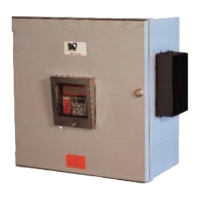
Control Panel
Panel Drawings (Located inside the control panel)
Instruction Manual (Located inside the control panel)
Warranty Card (Located inside the control panel)