Do you have a question about the NI cRIO-9058 and is the answer not in the manual?
Learn about required software and installation order for your cRIO-905x.
Details on LabVIEW versions, modules, and device drivers for different programming modes.
Details on the required DC external power supply for the cRIO-905x and its modules.
Guide to connect the power supply, including understanding POWER LED indicators.
Steps to connect the cRIO-905x to a host computer via USB for initial setup.
Steps to find and identify your cRIO-905x controller within the MAX software.
Procedure to set a system password for the cRIO-905x using MAX and the web utility.
Finalizing password changes and understanding recovery limitations.
Steps to install LabVIEW Real-Time software and device drivers onto the cRIO-905x.
Steps to complete the software installation wizard and verify the process.
Steps to troubleshoot and resolve cRIO-905x network connectivity problems.
| Processor Cores | 2 |
|---|---|
| Operating System | NI Linux Real-Time |
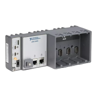
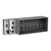
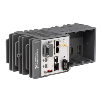
| Chassis Slots | 8 |
| DisplayPort | 1 |
| Memory (RAM) | 8 GB |
| FPGA | Xilinx Kintex-7 |
| Ethernet Ports | 2 |
| USB Ports | 2 |
| Serial Ports | 1 |
| Operating Temperature | -40 °C to 70 °C |
| Shock | 50 g, half-sine, 11 ms |
| Vibration | 5 g rms, 10 Hz to 500 Hz |
| Power Supply | 9 V to 30 V DC |