2
BETA DRAFT VERSION
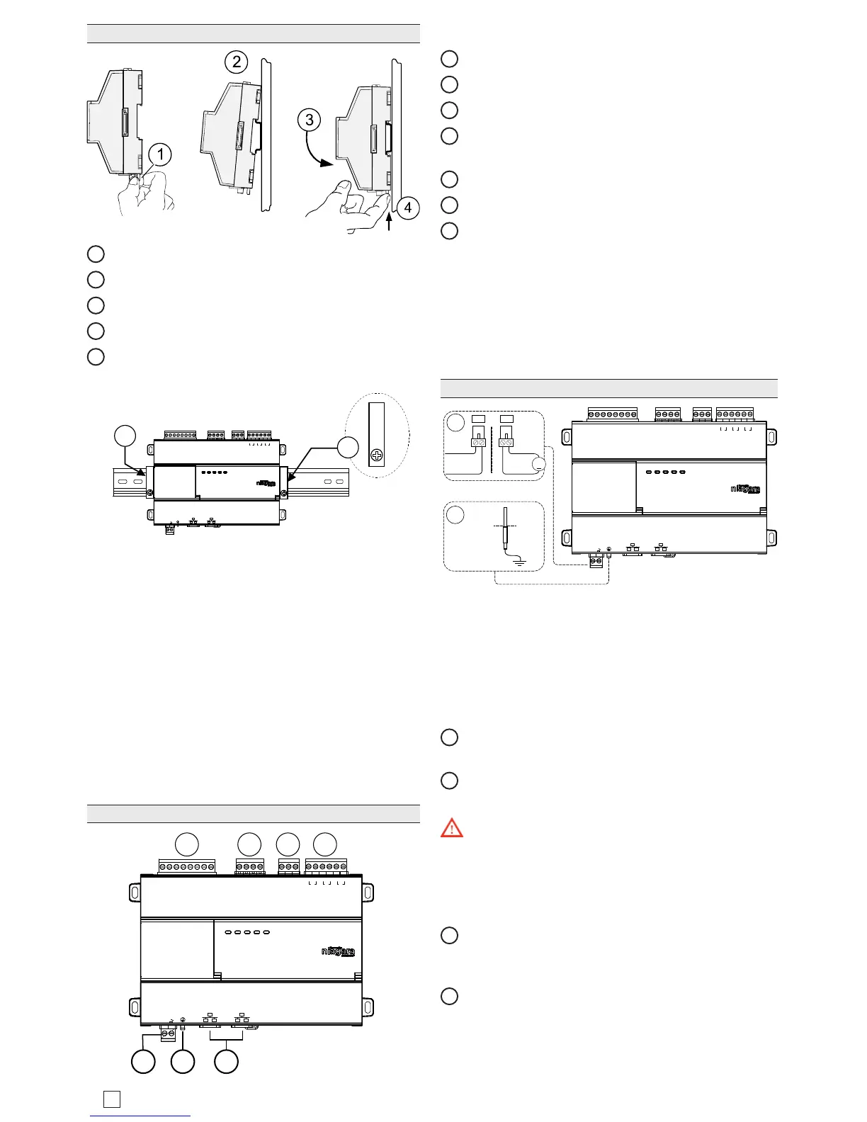
Mounting On DIN Rail
1
Pull the controller’s locking clip down.
2
Tilt the controller to hook over the DIN rail.
3
Push down and in on the unit to fasten to the rail.
4
Push locking clip up and click into place to secure.
5
Carefully secure both ends of the nal assembly with
DIN rail end-clips provided by the DIN rail vendor.
UNIVERSAL INPUTS
1UV0 U2U3U4U5 0V 0V
ANALOG OUTPUTS RS485
0V 0VAO2 AO1
S
A+
A-
24 VAC/DC
SEC PRI
GND
FACTORY
RESET
DEBUG
DIGITAL OUTPUTS
A BBABA
D3 D2 D1
5
5
Terminal Locations
e Edge-10 provides 5 Universal Inputs compatible
with 0–10Vdc, 0–20mA, dry contacts, 0–100K ohm
resistive, or Type 3 thermistor temperature sensors.
Edge-10 includes ve outputs as:
• ree digital triac outputs for on/o control of 24Vac
loads up to 1/2 Amp
• Two 0-10Vdc Analog Outputs for 0-10Vdc analog
control of loads at 2.5K ohm minimum or 4mA drain
maximum.
Wiring terminal positions are shown below, along with
LED locations.
Connector Locations
UNIVERSAL INPUTS
1UV0 U2U3U4U5 0V 0V
ANALOG OUTPUT RS485
0V 0VAO2 AO1
S
A+
A-
24 VAC/DC
GND
FACTORY
RESET
DEBUG
DIGITAL OUTPUTS
A BBABA
D3 D2 D1
SEC PRI
1 2 3 4
65 7
Field communications ports are as follows:
1
Universal inputs (5 inputs on 8-position connector)
2
Analog outputs (2 outputs on 4 position connector)
3
RS485 port (1 port on 3-position connector)
4
Digital (triac) outputs (3 outputs on 6-position con-
nector)
5
24Vac/dc input (1 input on 2-position connector)
6
Earth ground (1 tab for earth ground)
7
Ethernet ports (2, 10/100Mb, RJ-45 connectors with
integrated LEDs)
Wiring
Refer to “Connector Locations” and the following images
to locate connectors and other components. Descriptions
are provided for wiring to ground, to power, RS-485,
Ethernet, Inputs and Ouputs.
Wiring Earth Ground & Power
UNIVERSAL INPUTS
1UV0 U2U3U4U5 0V 0V
ANALOG OUTPUT
RS485
0V 0VAO2 AO1
S
A+
A-
24 VAC/DC
GND
FACTORY
RESET
DEBUG
DIGITAL OUTPUTS
A BBABA
D3 D2 D1
SEC PRI
24 Vac
50/60Hz
24 Vdc
+
1
2
Earth Ground
2.1
2.2
OR
Because the Edge-10 uses a half-wave rectied pow-
er supply, it should not share a transformer with the
JACE-8000, IO-R-34, or any legacy JACE.
Earth grounding provides protection from electrostatic
discharge or other forms of EMI.
NOTE: Depending on power source used.
2.1
(AC): Dedicated 24V transformer required, with nei-
ther side of the transformer secondary tied to ground.
2.2
(DC): Polarity is critical (uses onboard half wave
diode), - to ground and + to other terminal.
Warning: Before making power terminations, de-en-
ergize the 24V power source. Do not restore power until
completing all other mounting and wiring. See “Power up
and Initial Checkout”.
Prerequiste: A nearby earth grounding point.
1
Install the included earth ground wire to the control-
ler’s earth ground spade lug, and terminate the other
end to a nearby earth ground.
2
Unplug the controller’s 2-position power connector
plug and terminate the 24V supply source (AC or DC)
to the connector. Leave connector unplugged for now.