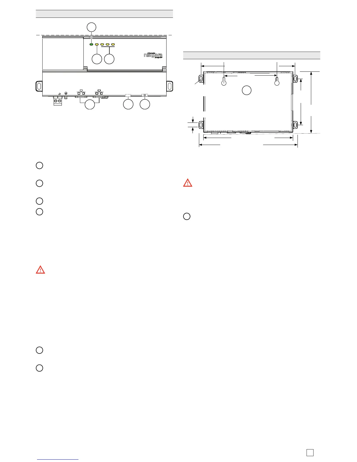
e controller has three yellow triac status LEDs, one
yellow heartbeat LED, and a single green controller
status LED located on the top of the controller. It also
includes two LEDs for each Ethernet port which are
located on the Ethernet connectors and are visible from
the side of the controller.
1
STAT (Green) - Remains illuminated while controller
is powered.
2
BEAT (Yellow) - “Heartbeat”, normally 1Hz, 50%
duty cycle.
3
D3, D2, D1:Active (Yellow), Inactive: (O).
4
SEC and PRI Ethernet , 2 LEDs for each port:
– Green LED on le: Link (On) / Activity (Flicker)
– Yellow LED on right: Speed; 100Mb(On) / 10
Mb(O).
If the “BEAT” LED stays illuminated constantly, does not
light, or blinks very fast, contact System Engineering for
technical support.
e 3Hz, 50%/50% on/o “BEAT” ash at bootup
also occurs during other critical operations, such as a
rmware upgrade to the controller and/or any attached
modules. To be safe, do not remove power from the
controller while its “BEAT” LED ashes with a 90%/10%
on/o duty cycle. Wait for the normal (50%/50%) ash
to return before removing power.
Along the bottom side of the controller is a debug port
for serial debug communications and a Factory Reset
button.
5
DEBUG - Micro-A USB for serial debug communica-
tions.
6
FACTORY RESET - Pushbutton switch to return the
controller to a factory default settings.
e DEBUG port is a standard Micro-A/B type USB port
for serial debug communications to the controller. Use a
serial terminal program (for example: PuTTY) to access
the controller “system shell” menu. is provides access
to some basic platform settings.
Default DEBUG port settings are: 115200, 8, N, 1 (baud
rate, data bits, parity, stop bits). For details on using a
serial connection to the DEBUG port, see the Edge-10
Install and Startup Guide or the JACE-8000 Install and
Startup Guide.
NOTE: Login requires admin-level platform credentials.
Default platform credentials are: username: “tridium”
password: “niagara”.
Tab Mounting option
1