4
BETA DRAFT VERSION
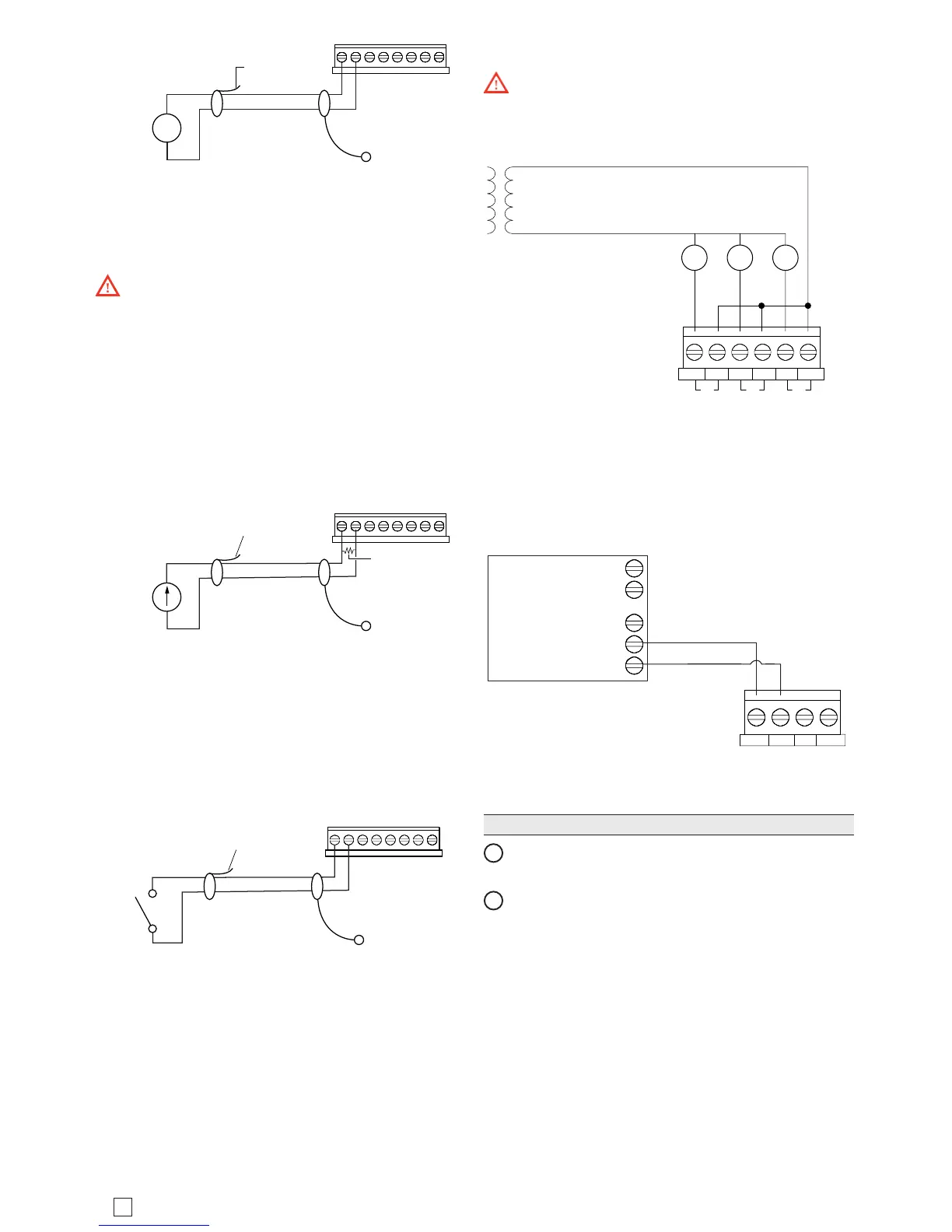
0V U5 U4 0V U3 U2 0V U1
Cut and tape
shield wire back
at sensor
Shielded, Twisted Cable,
61m (200 ft) maximum
- Stud in enclosure
Shield
Input Impedance > 5K ohms
0-10 Vdc Sensor
(self-powered sensor)
0-10
Vdc
+
-
4-20 mA
e inputs support self-powered 4–20 mA sensors. Input
accuracy is ±2% of span, without user calibration. Use a
499 ohm resistor wired across the input terminals.
Caution: When using an externally powered 4–20
mA sensor, be sure to de-energize its power supply
before making or changing any wiring connections to the
Edge-10 module. is is in addition to removing power
from the Edge-10 module. DO NOT apply external
power to the UI inputs without the 499 ohm resistor in
place. Otherwise, even a momentary application of power
(say, 24Vdc) to the UI terminals without the resistor may
damage circuitry on the Edge-10. Only aer completing
all input wiring should you restore power to such external
power supplies.
Cut and tape
shield wire back
at Thermistor
i
Shielded, Twisted Cable,
61m (200 ft) maximum
- Stud in enclosure
Shield
499 Ohm resistor
(supplied with unit)
4-20 mA Sensor
(self powered sensor)
Range: 0-20 mA
+
-
Binary Input
e universal inputs support normal dry (equipment
status) contacts. Standard dry contacts must have a 1 Hz.
(or less) COS frequency, with minimum dwell time >
500ms. (Contacts must remain open at least 500ms and
be closed at least 500ms.) Dry contacts support 11 Vdc
open circuits or 733 µA short-circuit current.
0V U5 U4 0V U3 U2 0V U1
Cut and tape
shield wire back
at sensor
Shielded, Twisted Cable,
61m (200 ft) maximum
- Stud in enclosure
Shield
Dry Contacts
Outputs
e Edge-10 provide 3 triac digital outputs and 2 0-10Vdc
analog outputs
Binary Triac Outputs
Each digital triac output is rated at 24 Vac +/- 15%,
50/60Hz, at 0.5A max. Relays are not rated for AC mains
(line level) powered loads (instead, 24V maximum).
Outputs are normally open, oating and do not share a
common pin.
NOTE: Triac outputs are suitable for AC only. DC loads
and dry contacts require an intermediate relay.
Warning: Never use a controller’s power transformer
to power I/O loads. Using the controller’s transformer
introduces potentially damaging switching transients into
the unit.
A BBABA
DIGITAL OUTPUTS
1
23
Only 24VAC loads
See Warning
Analog Outputs
Analog outputs (AO) are referenced by the terminals
labeled AOn and 0V (ground). Each AO can supply a
maximum of 4 mA over the entire 0 to 10Vdc range. e
minimum input impedance of a device controlled by an
AO must be greater than 2500 ohms.
0-10Vdc device
Input impedance is
greater than 2500 Ohms
Common (-)
Input (+)
ANALOG OUTPUT
Power up and Checkout
Power Up and Initial Checkout
1
Apply power by inserting the 2-position 24V power
connector plug.
2
Check the green STAT (Status) and yellow BEAT
(Heart- beat) LEDs.
When power is applied, the green “STAT” LED will light.
is indicates the system is OK, with power applied.
During bootup, the “BEAT” LED may blink at 3 Hz with
a 50%/50% on/o duty cycle. When bootup completes,
the platform daemon is started, and the normal 1 Hz
ash at 50%/50% on/ o duty cycle of the “BEAT” LED
returns.