3
BETA DRAFT VERSION
RS485 Wiring
UNIVERSAL INPUTS
1UV0 U2U3U4U5 0V 0V
ANALOG OUTPUT
RS485
0V 0VAO2 AO1
S
A+
A-
24 VAC/DC
GND
FACTORY
RESET
DEBUG
DIGITAL OUTPUTS
A BBABA
D3 D2 D1
SEC PRI
UNIVERSAL INPUTS
1UV0 U2U3U4U5 0V 0V
ANALOG OUTPUT
RS485
0V 0VAO2 AO1
S
A+
A-
24 VAC/DC
GND
FACTORY
RESET
DEBUG
DIGITAL OUTPUTS
A BBABA
D3 D2 D1
SEC PRI
Fox
MSTP
NRIO
- Fox
- BACnet/IP
- Modbus/TCP
- SNMP
1 3
2
Supervisor
IO-R-34
Device
Device
IO-R-34
S
+
–
-
+
S
Shielded twisted pair
RS-485
Ground at one
point on
Edge-10
end only
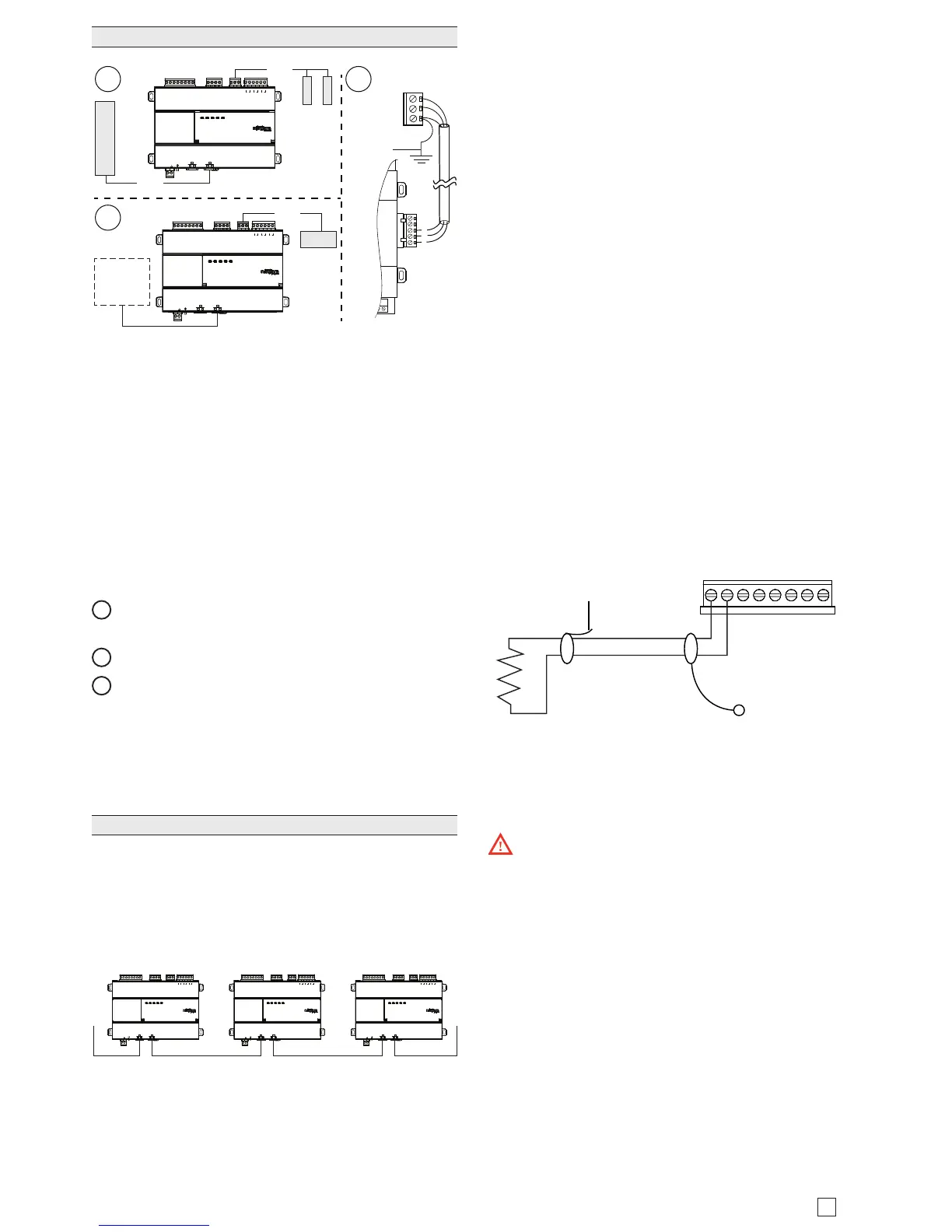
On the controller’s top side, a single, non-isolated, RS485
port provides connection to IO-R-34 module or to other
RS-485 devices (NRIO, MSTP, MODBUS). Do not use
this port to connect to other JACE controllers.
Use shielded, twisted-pair, 18-22 AWG cabling to wire in
a continuous multidrop fashion to other RS485 devices:
“minus to minus”, “plus to plus,” and “shield to shield.
10K bias resistors are permanently connected. Note that
there is no built in termination resistor. Maximum total
cable length is 1,000 feet (304.8 meters).
Connect the shield wire to earth ground at Edge-10 end
only. e image above shows example wiring.
1
RS485 port supporting a trunk of MSTP devices (3
devices max).
2
RS485 port connected to a single IO-R-34 module.
3
Example wire terminations to IO-R-34 using RS-485.
NOTE: Do not mix an IO-R-34 with other types of
RS485 devices on the same RS485 trunk.
NOTE: RS485 devices on the same network should use
the same protocol and baud rate. Up to 3 external devic-
es and 50 external points are supported.
Ethernet Wiring
Two RJ-45 10/100Mb Ethernet connectors are labeled
PRI for primary, and SEC for secondary. Use a standard
Ethernet patch cable to an Ethernet switch. ese ports
are suitable for daisy-chaining Edge-10 controllers (see
image below) or for connection to either a JACE-8000 or
directly to a network.
Daisy Chain using Ethernet
UNIVERSAL INPUTS
1UV0 U2U3U4U5 0V 0V
ANALOG OUTPUTS RS485
0V 0VAO2 AO1
S
A+
A-
24 VAC/DC
SEC PRI
GND
FACTORY
RESET
DEBUG
DIGITAL OUTPUTS
A BBABA
D3 D2 D1
UNIVERSAL INPUTS
1UV0 U2U3U4U5 0V 0V
ANALOG OUTPUTS RS485
0V 0VAO2 AO1
S
A+
A-
24 VAC/DC
SEC PRI
GND
FACTORY
RESET
DEBUG
DIGITAL OUTPUTS
A BBABA
D3 D2 D1
UNIVERSAL INPUTS
1UV0 U2U3U4U5 0V 0V
ANALOG OUTPUTS RS485
0V 0VAO2 AO1
S
A+
A-
24 VAC/DC
SEC PRI
GND
FACTORY
RESET
DEBUG
DIGITAL OUTPUTS
A BBABA
D3 D2 D1
Upon rst startup when IP connectivity is detected, the
Edge-10 initially requests an IP address via DHCP. If a
DHCP address is not found, the controller reverts to a
static IP address based on its serial number. e fallback
IP address is 192.168.1xx.xx, where xx.xx is the last 4
digits of the serial number. For example, if the serial
number is 123456789, the fallback IP address would be
192.168.167.89.
e default subnet mask is 255.255.0.0.
Inputs
Each of the 5 UI inputs supports any of the following:
• Type-3 10K ohm ermistor (see Caution on page 12)
• Resistive 0-100K ohms
• 0–10 Vdc
• 4–20 mA
• Binary Input
Thermistor
e inputs support 10K ermistor temperature sensors.
Input accuracy is in the range of ±1% of span. By default,
conversion is for a standard Type 3 thermistor sensor
with a sensor range of -10° to 135°F (-23.3° to 57.2°C).
Using a conversion type of “Tabular ermistor,” you
can specify a dierent thermistor response curve by
importing a thermistor curve .xml le. e Niagara kitIo
module contains an xml folder with thermistor curves
for a various thermistor temperature sensors. You can
also edit and export (for reuse) customized thermistor
curve xml les. See the NRIO Driver Guide for details.
0V U5 U4 0V U3 U2 0V U1
Cut and tape shield wire
back at Thermistor
Shielded, Twisted Cable,
61m (200 ft) maximum
- Stud in enclosure
Shield
10K Thermistor
Resistive 0-100K ohms
e inputs can read a resistive signal within a range from
0 to 100,000 ohms. Wiring is the same as shown for a
ermistor temperature sensor, above.
Caution: UI inputs provide optimum resis-
tive-to-temperature resolution in the 10K ohm range.
For a sensor with a range far from 10K ohms (such as a
100-ohm or 1000-ohm sensor), resolution is so poor as
to be unusable! To successfully use such a sensor, install
a transmitter that produces a Vdc or mA signal, and then
wire the transmitter to the UI according to the 0–10 Vdc
or 4–20 mA instructions.
0-10Vdc
e inputs support self-powered 0–10 Vdc sensors. Input
impedance is greater than 5K ohms.
0–10 volt accuracy is ±2% of span, without user calibra-
tion. 0–10.