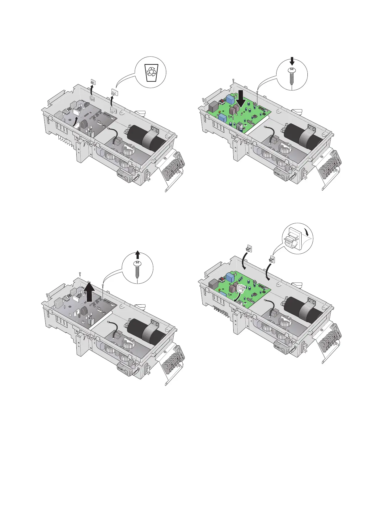
9.
Remove (break off) the grey mounts (3 pcs). New
mounts are enclosed. They are attached with double-
sided tape.
10.
Unscrew PWB2. The screws are countersunk below
the actual board, see the notches in the corners of
the circuit board. It is best to use a magnetic
screwdriver.
11.
Lift up both the inverter board PWB2 and cooling
fin.
12.
Place the new inverter board PWB2 with the cooling
fin in position in the distribution box.
13.
Secure the new inverter board PWB2 and the cool-
ing fin with the four screws in the corners. It is best
to use a magnetic screwdriver.
14.
Install the three new grey cable mounts using the
double-sided tape. (The opening must always face
upwards.)
13| GB
 Loading...