Do you have a question about the Nibe AMS 10 Series and is the answer not in the manual?
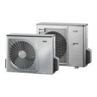
Defines the system configuration for AMS 10 with NIBE SPLIT Box.
Outlines installation and service procedures for specialists and safe appliance usage.
Explains symbols used in the manual (Note, Caution, Tip).
Lists critical safety measures for installation and operation.
Locates the service code and serial number (PF3) on the AMS 10 unit.
Instructions for proper disposal of packaging and used products.
Details refrigerant type (R410A) and its global warming potential.
A checklist for verifying refrigerant system and electrical installation.
Guidelines for transporting and storing the AMS 10 unit vertically.
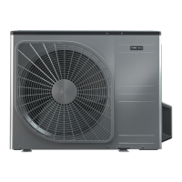
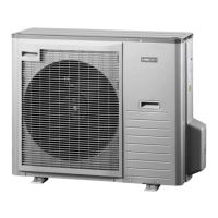
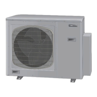
Instructions for positioning the outdoor unit on a suitable base, considering snow depth and noise.
Methods for moving the unit from street level to installation site.
Procedures for lifting the unit from its pallet to the final installation base.
Instructions for dismantling and scrapping the product in reverse order.
How to manage and drain condensation water from the unit.
Conditions under which the drain pan heater is powered.
Explains methods for managing condensation water drainage.
Shows routing condensation water to an indoor drain with a water seal.
Illustrates leading condensation water to a gutter with a water seal.
Describes positioning a stone caisson for condensation water drainage.
Specifies required clearance distances around the AMS 10 for installation and servicing.
Illustrates the process of removing outer covers for access to internal components.
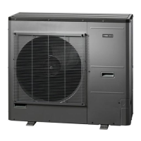
Identifies component locations within the AMS 10-6 outdoor unit.
Identifies component locations within the AMS 10-8 outdoor unit.
Identifies component locations within the AMS 10-12 outdoor unit.
Identifies component locations within the AMS 10-16 outdoor unit.
Lists and describes all components identified in the previous diagrams.
Shows component locations within the electrical panel for AMS 10-6 and AMS 10-8.
Lists and describes electrical components used in AMS 10.
Details the positioning of temperature sensors in outdoor modules.
Covers general requirements for electrical connections, including circuit breakers and wiring.
Shows a schematic of the electrical installation for the heat pump system.
General note about cable routing to prevent interference.
Illustrates the power connection for the AMS 10 outdoor unit.
Details connecting the communication cable to terminal block TB.
Refers to instructions for connecting accessories.
Explains the function of the compressor heater and pre-start requirements.
Lists alarms, their descriptions, and potential causes.
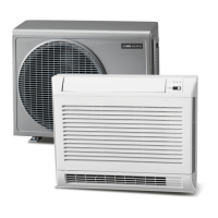
Lists accessory SPLIT boxes (HBS 05) for AMS 10.
Lists available lengths of condensation water pipes (KVR 10).
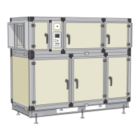
Lists control modules (SMO 20, SMO 40) for the system.
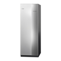
Lists various indoor modules (VVM 310, VVM320, VVM500) and their specifications.
Lists refrigerant pipe kits for different AMS 10 and HBS 05 models.
Lists ground stands and wall brackets for AMS 10 installation.
Provides dimensional drawings and measurements for AMS 10-6.
Details sound power and pressure levels for different AMS 10 models.
Lists detailed technical specifications for heating, cooling, and electrical data.
Presents SCOP and Pdesign values for AMS 10 according to EN 14825.
Shows the operating range for heating mode based on water and air temperatures.
Shows the operating range for cooling mode based on water and air temperatures.
Graphs showing heating output and COP for AMS 10-6 and AMS 10-8.
Graphs showing heating output for AMS 10-12 and AMS 10-16 with reduced fuse ratings.
Provides energy efficiency data for the AMS 10 package.
Electrical circuit diagram for the AMS 10-6 model.
Electrical circuit diagram for the AMS 10-8 model.
Electrical circuit diagram for the AMS 10-16 model.
Lists component designations and their descriptions.
An alphabetical index of topics and their corresponding page numbers.
Lists contact details for NIBE offices in various countries.