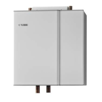
INSTALLING THE SHUNT
When installing the shunt, the flat side of the shaft must
be in the southwest position, see image. Then, install
the shunt motor with the knob in the middle position.
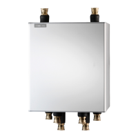
Shunt valve, (QN25)
Connection DN20 1 1/4" (22 mm)
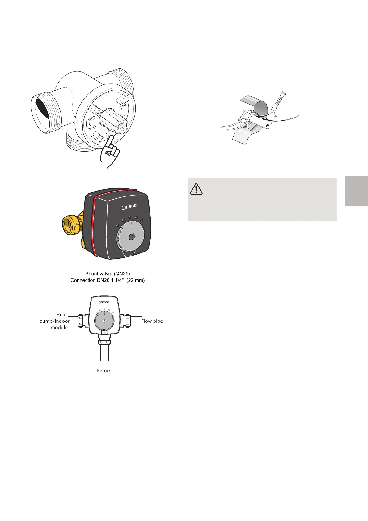
Return
Heat
pump/indoor
module
Flow pipe
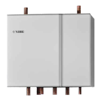
TEMPERATURE SENSOR
• The supply line sensor (EP21-BT2) is installed on the
pipe between the circulation pump (EP21-GP10) and
shunt valve (EP21-QN25).
• The return line sensor (EP21-BT3) is installed on the
pipe from the extra climate system.
Install the temperature sensors using cable ties, together
with the heat conducting paste and aluminium tape.
Then insulate with the enclosed insulation tape.
NOTE
To prevent interference, sensor cables to ex-
ternal connections must not be laid close to
high voltage cables.
25ECS 40/ECS 41 F-series | GB
F

 Loading...