Electrical connection
NOTE
All electrical connections must be carried out
by an authorised electrician.
Electrical installation and wiring must be carried
out in accordance with the stipulations in force.
The climate unit must not be powered when
installing ECS 40/ECS 41.
• To prevent interference, sensor cables to external
connections must not be laid close to high voltage
cables.
• The minimum area of communication and sensor
cables to external connections must be 0.5 mm² up
to 50 m, for example EKKX, LiYY or equivalent.
• ECS 40/ECS 41 must be installed via an isolator
switch. The cable area has to be dimensioned based
on the fuse rating used.
• Mark the relevant electrical cabinet with a warning
about external voltage, in those cases where a com-
ponent in the cabinet has a separate supply.
• ECS 40/ECS 41 restarts after a power failure.
The electrical circuit diagram is at the end of this Installer
handbook.
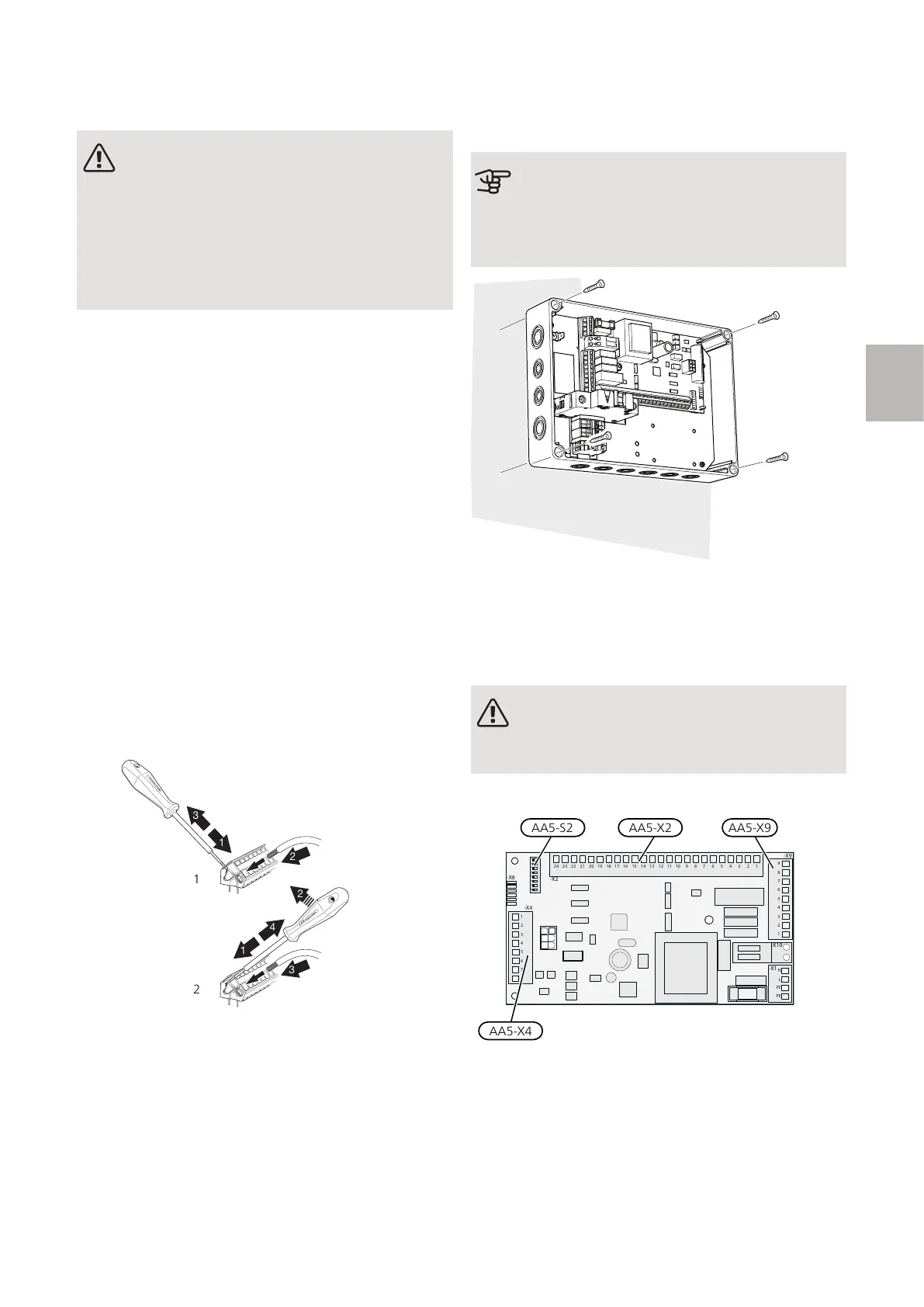
CABLE LOCK
Use a suitable tool to release/lock cables in terminal
blocks.
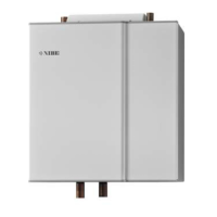
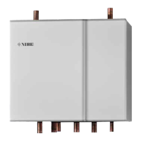
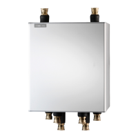
MOUNTING
The AXC module (AA25) is a separate, electric control
module and must be mounted on a wall.
Caution
The screw type must be adapted to the surface
on which installation is taking place.
Installation is not permitted using glue or tape.
Use all mounting points and mount the module upright,
flat against the wall.
Leave at least 100 mm of free space around the module
to allow access and make cable routing easier during
installation and servicing.
NOTE
The installation must be carried out in such a
way that IP21 is satisfied.
OVERVIEW ACCESSORY BOARD (AA5)
ON
1 2 3 4 5 6 7 8
-X9
-X2
24 20212223 1516171819 1011121314 56789 1
1
N
L
PE
PE
1
2
3
4
5
6
7
8
2
3
4
5
6
7
8
9
234
-X8
-X4
-X10
-X1
AA5-X2 AA5-X9AA5-S2
AA5-X4
13ECS 40/ECS 41 S-series | GB
S
 Loading...