Pipe connections
INSTALLATION PRINCIPLE
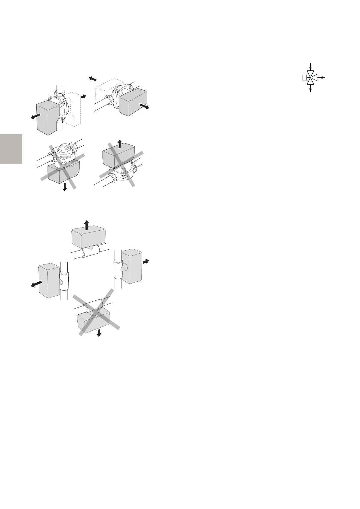
CIRCULATION PUMP
The circulation pump’s permitted positions.
SHUNT
The shunt’s permitted positions.
GENERAL
When connecting extra climate systems, they must be
connected so that they have a lower working temperat-
ure than the climate system 1.
CIRCULATION PUMP
The extra circulation pump (EP21-GP10) is positioned in
the extra climate system according to the outline dia-
gram.
SHUNT VALVE
The shunt valve (EP21-QN25) is located on the supply
line after the heat pump/indoor module, before the first
radiator in the climate system 1. The return line from
the extra climate system is connected to the shunt valve
and to the return line from the climate system 1, see
image and outline diagram.
• Connect the supply line to the climate
system from the heat pump to port A on
the shunt valve (opens on increase signal)
• Connect the return line from the climate
system to port B on the shunt valve via
the T-pipe (closes on reduce signal).
• Connect the supply line to the climate system to the
common port AB on the shunt valve (always open).
ECS 40/ECS 41 S-series | GB6
S
 Loading...