EasyManuals Logo

Nibe F1155 Series User Manual

Nibe F1155 Series
84 pages
To Next Page IconTo Next Page
To Previous Page IconTo Previous Page
Page #21 background imageLoading...
Page #21 background image
F1255
FQ10
FC1
FQ10-SF2
UB2
UB1
UB3
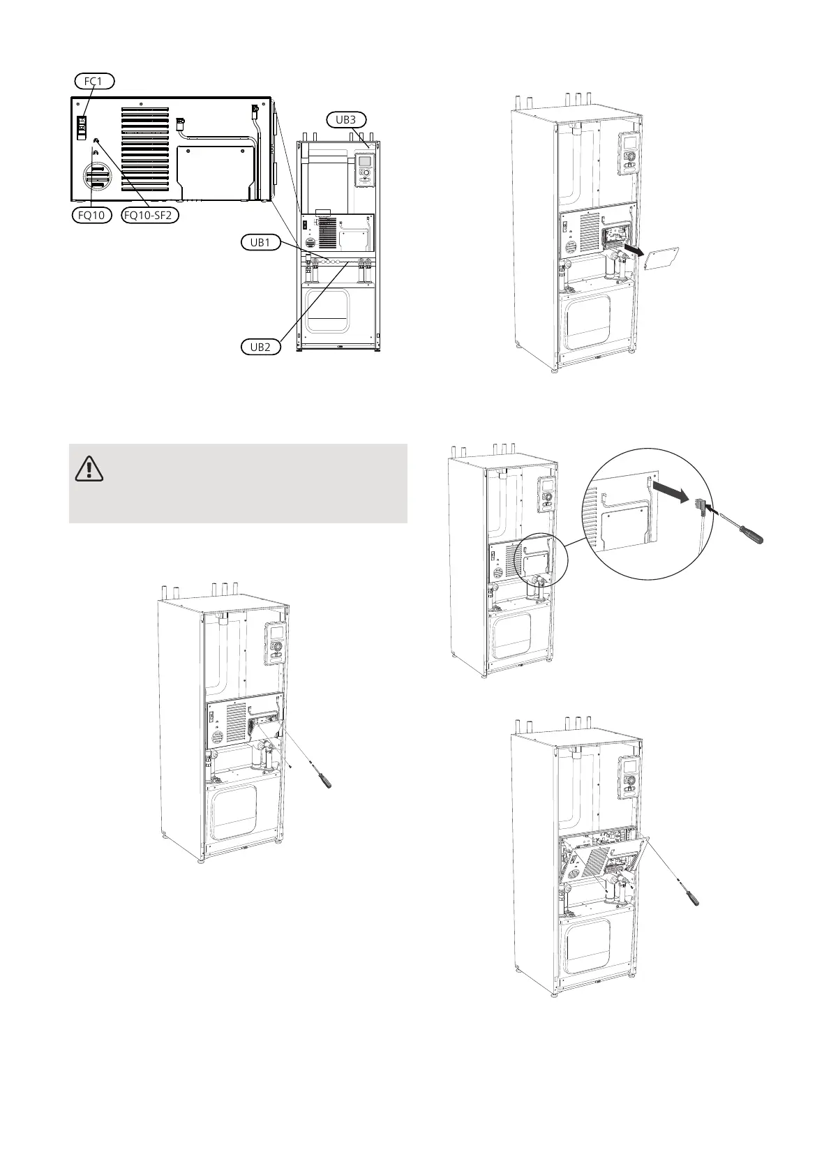
ACCESSIBILITY, ELECTRICAL CONNECTION
The plastic cap of the electrical boxes is opened using
a screwdriver.
NOTE
The cover for the input card is opened without
a tool.
Removing the cover, input circuit board
1.
Unscrew the screws and angle out the cover.
L
E
K
L
E
K
L
E
K
L
E
K
2.
Pull off the cover.
L
E
K
L
E
K
L
E
K
L
E
K
Removing the hatch, electrical cabinet
1.
Disconnect the contacts.
L
E
K
2.
Unscrew the screws and angle out the cover.
L
E
K
L
E
K
L
E
K
L
E
K
21Chapter 5 | Electrical connectionsNIBE F1155

Other manuals for Nibe F1155 Series

Questions and Answers:

Question and Answer IconNeed help?

Do you have a question about the Nibe F1155 Series and is the answer not in the manual?

Nibe F1155 Series Specifications

General IconGeneral
RefrigerantR410A
Control SystemNIBE SMO 40
InstallationIndoor
Heating Capacity1.5-16 kW
Cooling CapacityNot applicable
Power Input CoolingNot applicable
EER CoolingNot applicable
Weight Outdoor UnitNot applicable
Dimensions Outdoor Unit (HxWxD)Not applicable
Dimensions Indoor Unit (HxWxD)600 x 620 mm

Related product manuals