This automatic control occurs when the compressor is
running and sets the speed of the brine pump so that
the optimum temperature difference between the supply
and return lines is attained.
Heating medium side
To set the correct flow in the heating medium system,
the heating medium pump must run at the correct
speed. F1155 has a heating medium pump that can be
automatically controlled in standard mode. Certain
functions and accessories may require it to run manually
and the correct speed must then be set.
This automatic control occurs when the compressor is
running and sets the speed of the heating medium
pump, for the relevant operating mode, so the optimum
temperature difference between the supply and return
lines is achieved. During heating operation, the set DOT
(dimensioned outdoor temperature) and temperature
differential in menu 5.1.14 are used. If necessary, the
maximum speed of the circulation pump can be limited
in menu 5.1.11.
Pump adjustment, manual operation
Brine side
F1155 has a brine pump that can be automatically con-
trolled. For manual operation: deactivate "auto" in menu
5.1.9 and then set the speed according to the diagram
below.
Caution
When an accessory for passive cooling is used,
the brine pump speed must be set in menu
5.1.9.
Set the pump speed when the system has come into
balance (ideally 5 minutes after compressor start).
Adjust the flow so the temperature difference between
brine out (BT11) and brine in (BT10) is between 2 - 5 °C.
Check these temperatures in menu 3.1 "service info"
and adjust the brine pump’s (GP2) speed until the tem-
perature difference is obtained. A large difference indic-
ates a low brine flow and a small difference indicates a
high brine flow.
Available pressure, kPa
Electrical output, W
0
0,0 0,05 0,10 0,15 0,20 0,25 0,30 0,45
10
20
30
40
50
60
Tillgängligt tryck, kPa
Eleffekt, W
Flöde l/s
P100%
P80%
P60%
P40%
Tillgängligt tryck, kPa
Eleffekt, W
1
2
3
4
70
80
0,35
0,40
p
F1155 6 kW
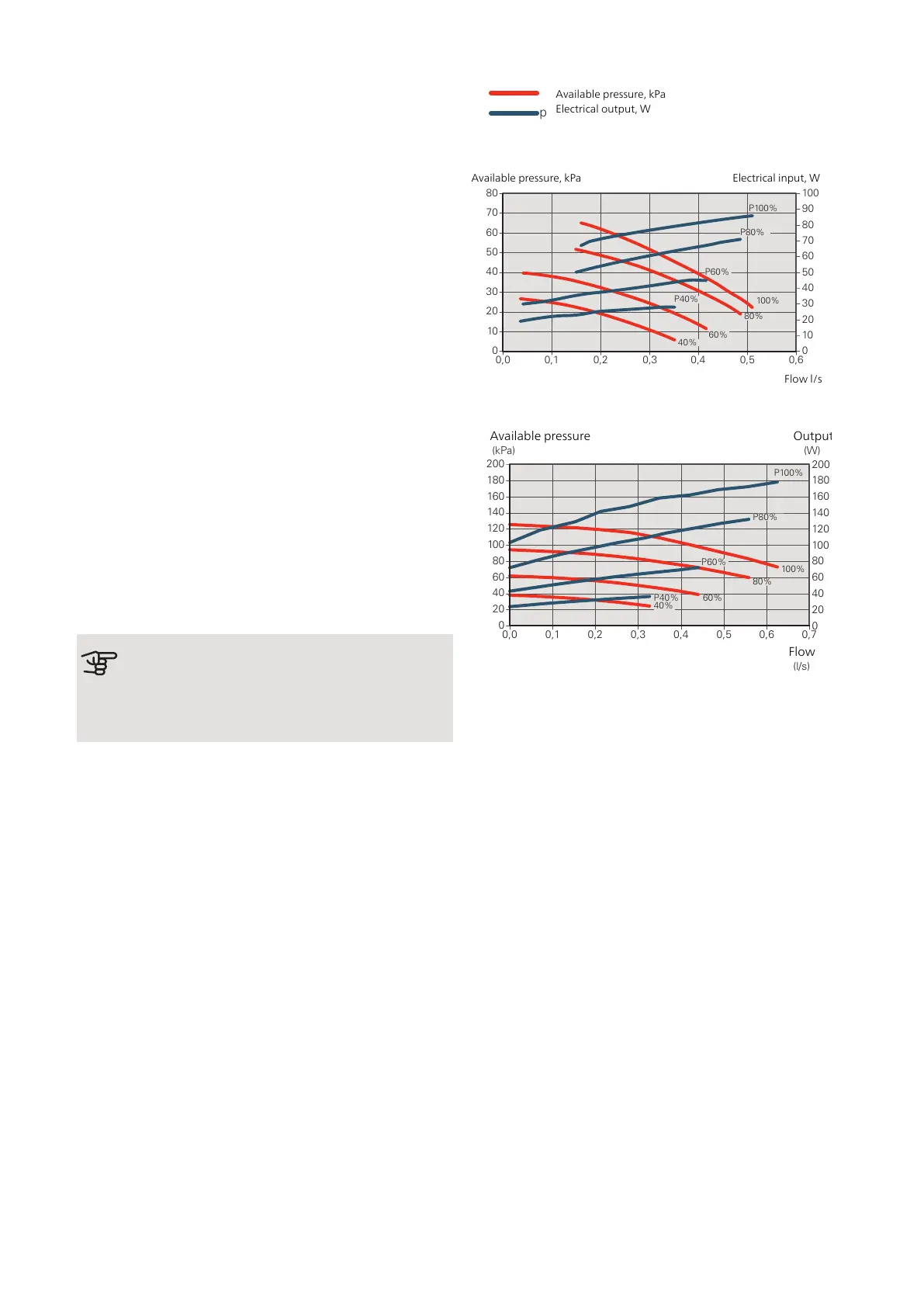
Available pressure, kPa
Flow l/s
Electrical input, W
Pumpkapacitet, köldbärarsida för F1155-1255 -6 kW, manuell drift.
Tillgängligt tryck
kPa
Eleffekt
W
0
0,0 0,1 0,2 0,3 0,4 0,5 0,6
30
20
10
40
50
60
70
80
0
100
90
80
70
60
50
40
30
20
10
Flöde l/s
P100%
P80%
100%
80%
60%
40%
P40%
P60%
F1155 12 kW
(kPa)
(W)
Flöde
(l/s)
0
0,0 0,1 0,2 0,3 0,4 0,5 0,6 0,7
40
20
60
100
160
140
80
120
180
200
0
80
60
40
20
100
120
140
160
180
200
40%
60%
80%
100%
P100%
P80%
P40%
P60%
Available pressure
Flow
Output
Heating medium side
F1155 has a heating medium pump that can be automat-
ically controlled. For manual operation: deactivate "auto"
in menu 5.1.11 and then set the speed according to the
diagrams below.
The flow must have a suitable temperature difference
for the operating case (heating operation: 5 - 10 °C, hot
water generation: 5 - 10 °C, pool heating: approx. 15 °C)
between controlling supply temperature sensor and re-
turn line sensor. Check these temperatures in menu 3.1
“service info” and adjust the heating medium pump
(GP1) speed until the temperature difference is attained.
A high difference indicates a low heating medium supply
and a low difference indicates a high heating medium
supply.
NIBE F1155Chapter 6 | Commissioning and adjusting32

 Loading...


