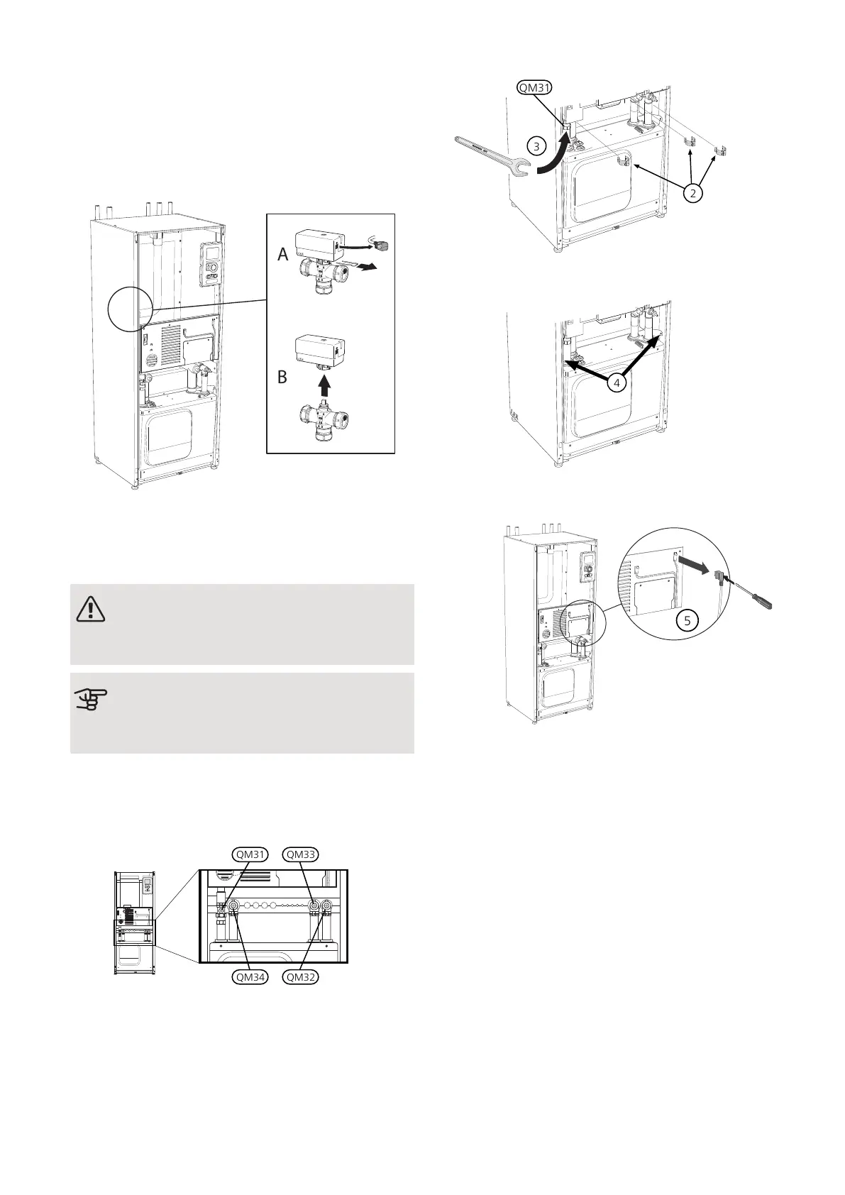
REMOVE THE MOTOR ON THE SHUTTLE
VALVE
The motor on the shuttle valve can be removed to facil-
itate servicing.
• Disconnect the cable from the motor and remove the
motor from the shuttle valve as illustrated.
PULLING OUT THE COOLING MODULE
The cooling module can be pulled out for service and
transport.
NOTE
Switch off the heat pump and cut the power
with the safety switch.
Caution
Remove the front cover according to the de-
scription on page 9.
1.
Close the shut-off valves (QM31), (QM32), (QM33)
and (QM34).
Drain the compressor module according to the in-
structions on page 56
2.
Pull off the lock catches.
3.
Disconnect the pipe connection under the shut-off
valve (QM31).
4.
Remove the two screws.
5.
Remove the connection from the base card (AA2)
using a screwdriver.
6.
Disconnect the connectors (A) and (B) from the un-
derside of the base card cabinet.
7.
Disconnect the connector (C) from the electric addi-
tion PCB (AA1) using a screwdriver.
8.
Disconnect the switch (D) from the joint board
(AA100).
9.
Carefully pull out the cooling module.
NIBE F1155Chapter 9 | Service58

 Loading...


