CONNECTING EXTERNAL OPERATING
VOLTAGE FOR THE CONTROL SYSTEM
NOTE
Mark up any junction boxes with warnings for
external voltage.
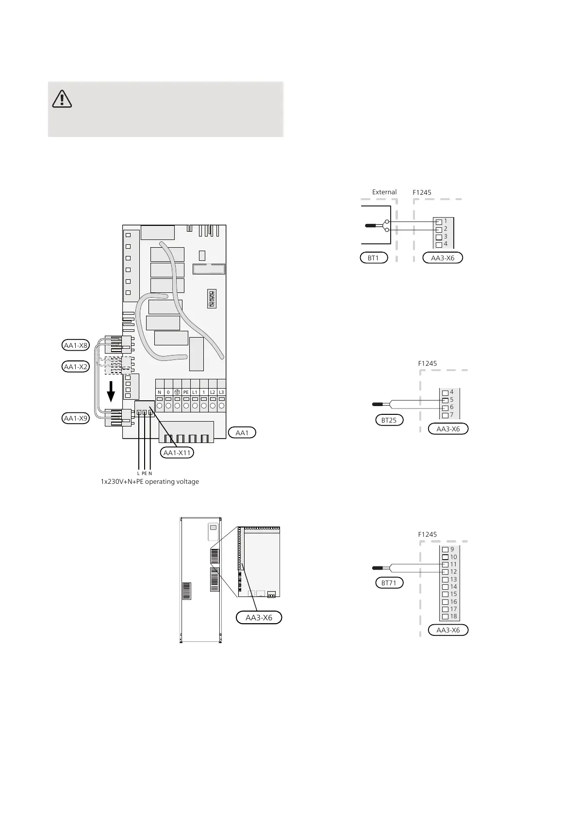
If you wish to connect external operating voltage for the
control system to F1245 on the immersion heater circuit
board (AA1) the edge connector at AA1:X2 must be
moved toAA1:X9 (as illustrated).
Operating voltage (1x230V ~ 50Hz) is connected to
AA1:X11 (as illustrated).
ON
L1 1 L2 L3PE
PE
0N
NL
1x230V+N+PE
1x230V+N+PE operating voltage
AA1
AA1-X8
AA1-X2
AA1-X9
AA1-X11
CONNECTING SENSORS
Connect the sensor(s) to
terminal X6 on input
board(AA3) according to the
instructions below.
Outside sensor
Install the outdoor temperature sensor (BT1) in the
shade on a wall facing north or north-west, so it is unaf-
fected by the morning sun for example.
Connect the sensor to terminal block X6:1 and X6:2 on
the input board (AA3). Use a twin core cable of at least
0.5 mm² cable area.
If a conduit is used it must be sealed to prevent condens-
ation in the sensor capsule.
Temperature sensor, external flow line
If temperature sensor, external flow line (BT25) needs
to be used, connect it to terminal block X6:5 and X6:6
on the input card (AA3). Use a 2 core cable of at least
0.5 mm² cable area.
Temperature sensor, external return line
If temperature sensor, external return line (BT71) needs
to be used, connect it to one of the AUX inputs on the
input board (AA3). Use a 2 core cable of at least 0.5 mm²
cable area.
BT71
F1245
14
13
12
11
10
9
18
15
16
17
Room sensor
F1245 is supplied with a room sensor enclosed (BT50).
The room sensor has a number of functions:
1.
Shows current room temperature in the display on
F1245.
2.
Option of changing the room temperature in °C.
3.
Provides the option of fine-tuning the room temper-
ature.
NIBE F1245Chapter 5 | Electrical connections24

 Loading...


