FIGHTER 1120/1220
Switch
with three positions 1 - 0 - :
1 Normal mode. All control functions connected.
0 The boilers is completely switched off.
Standby. Only the circulation pump and possibly
the electrical addition. Not connected at the factory.
The switch must not be turned to “1” or “ ” before
filling the boiler with water.
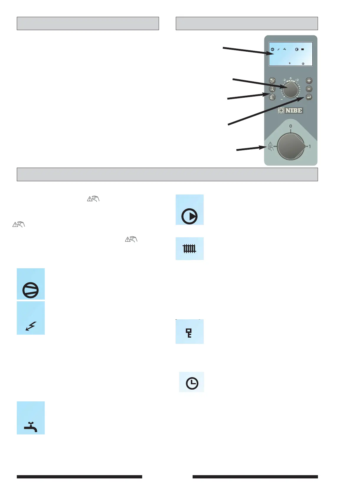
Display
Switch
Left
keypad
Heating
curve offset
Display
First row:
Compressor symbol
Indicates when the compressor is opera-
tional.
Addition symbol
Indicates when the immersion heater is
connected. The line indicates which power
step/steps are currently connected.
I Step 1 is connected.
II Step 2 is connected.
III Step 3 is connected.*
I II Steps 1+2 are connected.
II III Steps 2+3 are connected.*
I III Steps 1+3 are connected.*
I II III Steps 1+2+3 are connected.*
Hot water symbol.
Tap is shown when the heat pump charges
the hot water.
A is shown when a temperature increase is
in progress.
B is shown when a time based temperature
increase is in progress, for example, peri-
odic. Factory setting is
60 °C every 14
days.
Right
keypad
Front Panel
Circulation pump symbol.
I Shown when the circulation pump is
operational.
II Shown when circulation pump 2 is ope-
rational (the accessory ESV 20 is
required).
Heating system symbols
Shown when house heating is in progress.
Second row: Value of the current parameter.
Third row: Description of current display para-
meter. “Hot water temp” is normally
shown.
Fourth row: Shows menu numbers, key lock,
clock symbol and time
A key lock can be activated in the main
menus by simultaneously pressing the
plus and the minus buttons. The key sym-
bol will then be shown on the display. The
same procedure is used to deactivate the
key lock.
The symbol becomes visible when a timer
function is selected, for example, periodic
lowering of the supply or time setting for
extra hot water.
Explanation
 Loading...


