4 NIBE PB 10
Installation
General information for the installer
General information for the installer
The boiler room where the equipment is to be installed
must be in accordance with the applicable fire safety regu-
lations.
Check points before installation:
Q Contact a chimney sweep to obtain approval that the
chimney can be used for pellet firing, and that the loca-
tion of the installation meets the applicable fire safety
regulations.
Q Contact the building and environmental office in your
district for basic building permits/notices about the
installation.
Assembly
The equipment must be positioned so that there is suf-
ficient space for cleaning and sweeping the burner, boiler
and flue.
The internal diameter of the chimney should be at least
125 mm. The recommended minimum chimney height for
this diameter is 6 m at 18 – 20 kW output.
Before installing the mounting frame (A) in the suitable
door opening on the boiler, the mounting holes for attach-
ment to the boiler must be drilled in the mounting frame,
screw the supplied counter sunk screws securely to the
mounting frame. If the swing arm is to be used, install it
on the mounting frame, then screw the mounting frame
securely to the boiler.
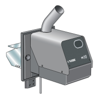
Install the burner in front of the boiler's water jacket. The
burner has an extended cover that directs the flame for-
ward. For installation in boilers without a spacer connector,
the extended cover can be cut to direct the flame upwards.
The distance from the bed of embers to the nearest boiler
surface must be 200 – 250 mm. This is so that the flame
has enough space and for optimum combustion.
Screw the burner to the cover frame using the supplied
knobs.
The connection between the burner and boiler must be
sealed, to prevent drafts and flue gas escaping.
The burner is set at the factory for 8 mm pellets of good
quality, approx. 12 kW supplied output at a screw angle of
45°.
The hose must be bent slightly and the hose connections
offset slightly from each other.
After the screws have been placed in the pellet reservoir or
store, refill with pellets and start the installation.
When the burner is installed on the boiler, an authorised
electrician must connect the electrical terminals to the
boiler's double thermostat according to the supplied wiring
diagram, (see wiring diagram) the power supply cable can
be separated. All connections to the burner must be made
via contacts in the chassis.
After the screws have been placed in the pellet reser-
voir or store with pellets and start the installation. See
"Commissioning and adjusting".
2
1
b
a
r
3
0
4
T
G
20
1
00
4
0
8
0
60
°
C
0
1
20
T
G
P
T
°
C
°
C
4
0
5
0
6
0
7
0
9
0
8
0
1
0
2
0
3
0
6
0
70
8
0
4
0
5
0
45°
Alt. 1
Alt. 2
LEK
MR
MR
A
 Loading...