Pipe connections
General
When POOL 40 is connected to the climate unit, the
heating circuit must be supplied with an external circu-
lation pump. This is because, during pool charging, the
heat pump’s internal circulation pump maintains the
flow through the pool heat exchanger. The extra/extern-
al circulation pump (GP10) maintains the flow in the
heating circuit, so the supply temperature sensor (BT25)
can measure the temperature correctly.
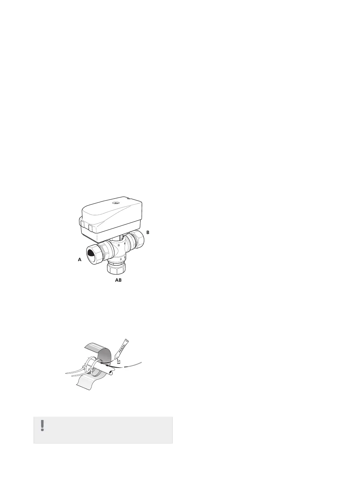
Shuttle valve
■
Install the reversing valve (QN19) with port AB as in-
coming supply line from the heat pump, port A to-
wards the pool and port B towards the heating system.
Install it so that port AB is open towards port B when
the motor is in standby mode. In the event of a signal,
port AB opens towards port A.
Temperature sensor
■
The pool sensor (BT51) is placed on the return line from
the pool.
■
The external flow temperature sensor (BT25) is located
on the flow line to the climate system, after the circu-
lation pump (GP10).
Install the temperature sensors with cable ties with the
heat conducting paste and aluminium tape. Then insu-
late with supplied insulation tape.
NOTE
Sensor and communication cables must not be
placed near power cables.
Function
Heating of the pool is prioritised according to selected
settings in the heat pump.
If the pool sensor (BT51) is not connected, pool charging
is not permitted to start.
The heating medium flow is adjusted so that the temper-
ature difference over the pool heat exchanger is
10–15 °C. The setting is made in menu 5.1.11.
POOL 40 | GB14