Indoor module ACVM 270
႑
It is recommended that ACVM 270 is installed in a room
with existing floor drainage, most suitably in a utility
room or boiler room.
႑
The surface must be firm, preferably a concrete floor or
foundation.
႑
Install ACVM 270 with its back to an outside wall, ideally
in a room where noise does not matter. If this is not
possible, avoid placing it against a wall behind a bed-
room or other room where noise may be a problem.
႑
The unit can be aligned using the adjustable feet.
႑
Route pipes so they are not fixed to an internal wall that
backs on to a bedroom or living room.
႑
Ensure that there is approx. 500 mm free space in front
of and 220 mm above the product for any future service.
Dimensioning expansion vessel
Internal volume in ACVM 270 for calculating expansion
vessel is 280 l. The expansion vessel's volume must be at
least 5 % of the total volume.
Example table
Volume Expansion vessel (l)Total volume (l)
14280
16320
18360
Initial pressure and max height difference
The initial pressure of the pressure expansion vessel must
be dimensioned according to the maximum height (H)
between the vessel and the highest positioned radiator,
see figure. An initial pressure of 0.5 bar (5 mvp) means a
maximum permitted height difference of 5 m.
If the standard initial pressure in the pressure vessel is not
high enough it can be increased by filling via the valve in
the expansion vessel. The expansion vessel's standard initial
pressure must be entered in the check list on page 34.
Any change in the initial pressure affects the ability of the
expansion vessel to handle the expansion of the water.
H
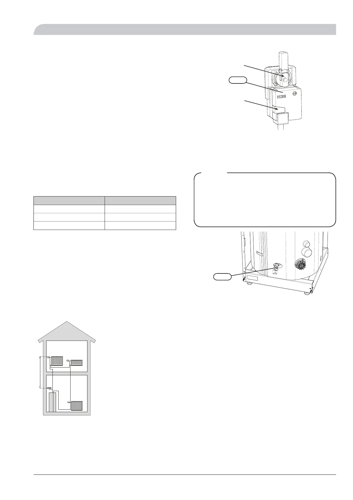
Manual shunting
When ACVM 270 is set to emergency mode, the heating
control system is not in operation, and manual shunt op-
eration is required.
1.
Depress and lock the button on (QN11).
2.
Turn the mixing valve to the desired position by hand.
Button
Knob
QN11
Emptying the vessel
The vessel in ACVM 270 is emptied by opening the valve
(QM1) and safety valve (FL2).
NOTE
When the vessel in ACVM 270 is emptied via the valve
(QM1), some water will remain in the coil and in the
heat exchanger.
This means that there is a risk of the heat exchanger,
pipes and valves freezing at low temperatures as well
as a hygienic risk for the coil in the hot water section.
40
Recommended installation order
1.
Connect ACVM 270 to the climate system, cold and
hot water lines as well as any external heat sources.
See page 18. Also see docking descriptions on page
22 and further on.
2.
Install the refrigerant pipes according to the descrip-
tion on page 19.
3.
Connect the load monitor, outdoor temperature
sensor, any centralised load control and external con-
tacts as well as the cable between ACVM 270 and AMS
10. See page 28.
4.
Connect supply to ACVM 270. See page 27.
5.
Follow the commissioning instructions on page 32.
17NIBE™ SPLIT
For the Installer
General information for the installer