the current would exceed the specified main fuse, the power
step is not permitted. The size of the property’s main fuse
is specified in menu 7.1.9 - "Load monitor".
Load monitor with current sensor
When many power-consuming products are connected in
the property at the same time as the electric additional heat
is operating, there is a risk that the property’s main fuse will
trip. VVM S320 is equipped with a load monitor that, with
the help of a current sensor, controls the power steps for
the electric additional heat by redistributing the power
between the different phases or disengages the electric
additional heat if there is an overload in a phase. Reconnec-
tion occurs when the other current consumption drops.
Caution
Activate phase detection in menu 7.1.9 for full
functionality, if current sensors are installed.
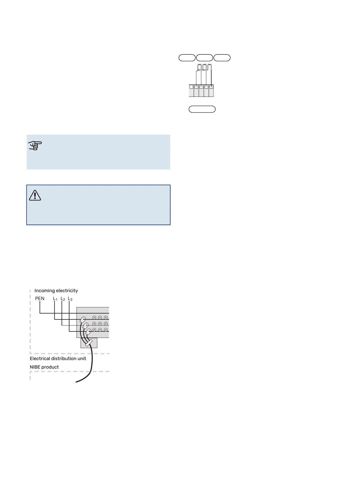
Connecting current sensors
NOTE
If the installed air/water heat pump is frequency
controlled, it will be limited when all power stages
are disconnected.
A current sensor should be installed on each incoming phase
conductor in to the distribution box to measure the current.
The distribution box is an appropriate installation point.
Connect the current sensors to a multi-core cable in an en-
closure directly adjacent to the electrical distribution unit.
The multi-core cable between the enclosure and VVM S320
must have a cable area of at least 0.5 mm².
Electrical distribution unit
NIBE product
Incoming electricity
Connect the cable to terminal block AA2-X30:9-12, where
X30:9 is the common terminal block for the three current
sensors.
+5V
BE1
BE2
BE3
BE1 BE2 BE3
11
10
9
8
12
GND
AA2-X30
23Chapter 5 | Electrical connectionsNIBE VVM S320

 Loading...


