COMMUNICATION
Communication with air/water heat pump
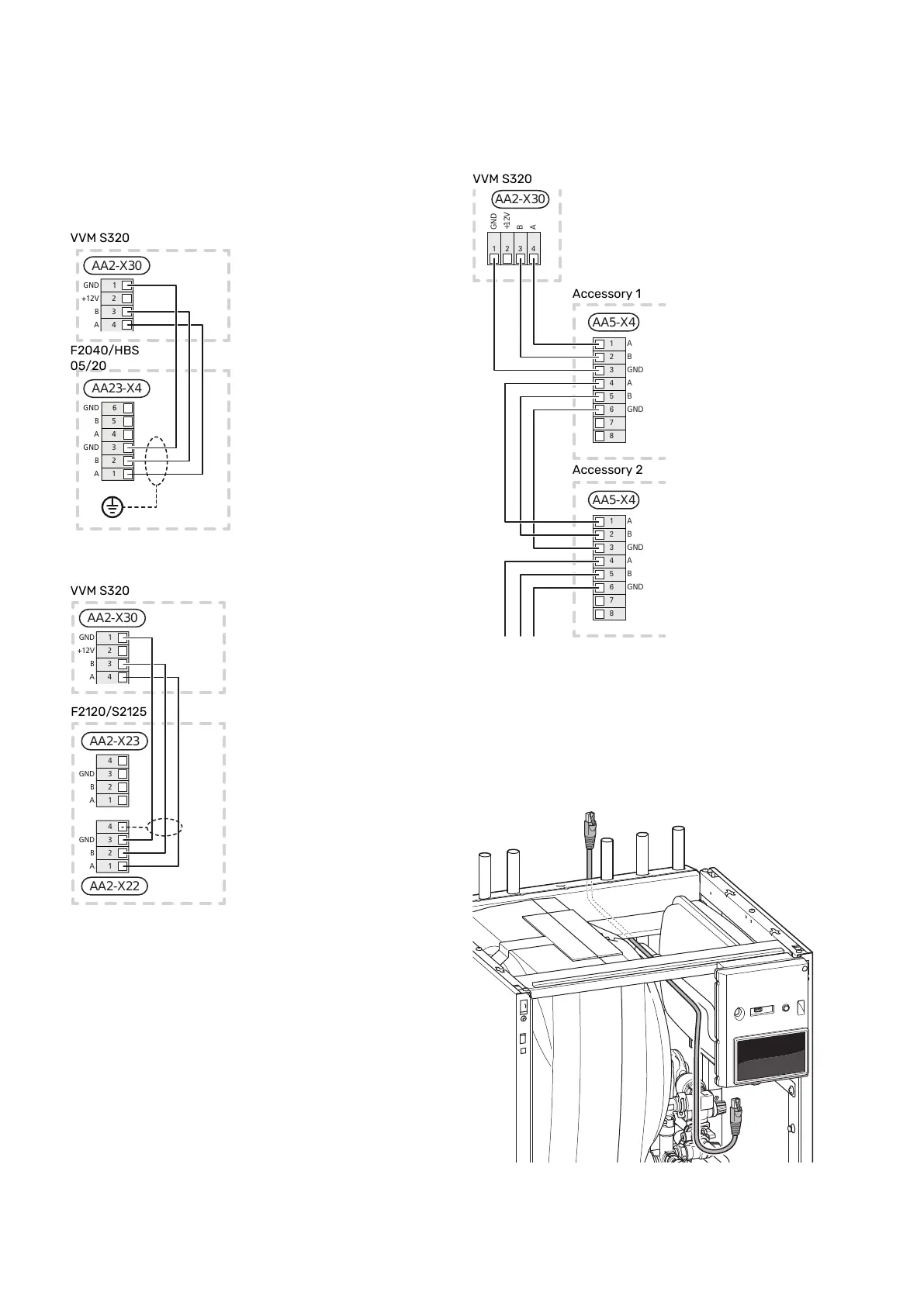
If the air/water heat pump is to be connected to VVM S320,
this is connected to terminal block X30:1 (GND), X30:3 (B)
and X30:4 (A) on the PCB AA2.
VVM S320 and F2040 / NIBE SPLIT HBS
AA23-X4
B
A
GND
B
A
GND
5
4
3
2
1
6
Inomhusmodul
AA2-X30
+12V
B
A
GND
2
3
4
1
F2040 / HBS 05
VVM S320 and F2120 / S2125
AA2-X22
AA2-X23
Inomhusmodul
F2120
3
2
1
4
GND
GND
A
A
B
B
3
2
1
4
AA2-X30
+12V
B
A
GND
2
3
4
1
Connecting accessories
Instructions for connecting accessories are provided in the
manual accompanying the accessory. See section "Accessor-
ies" for a list of the accessories that can be used with
VVM S320. Connection for communication with the most
common accessories is shown here.
Accessories with accessory board (AA5)
Accessories with accessory board (AA5) connect to terminal
block AA2-X30:1, 3, 4 in VVM S320.
If several accessories are to be connected, or are already
installed, the boards are connected in series.
Because there can be different connections for accessories
with accessory board (AA5), you should always read the in-
structions in the manual for the accessory that is to be in-
stalled.
B
A
GND
+12V
AA2-X30
1 2 3 4
AA5-X4
1
2
3
4
5
6
7
8
A
B
GND
A
B
GND
AA5-X4
1
2
3
4
5
6
7
8
A
B
GND
A
B
GND
Accessory 1
VVMS320
Accessory 2
Network cable for myUplink (W130)
In instances when you want to connect to myUplink using
a network cable instead of via wifi.
1. Connect the shielded network cable to the display.
2. Route the network cable to the top of VVM S320.
3. Follow the flow meter’s cable out at the rear.
NIBE VVM S320Chapter 5 | Electrical connections24

 Loading...


