1
1
GENERAL SAFETY WARNINGS AND
PRECAUTIONS
1.1 - Safety warnings
• CAUTION! - This manual contains important instructions and warn-
ings for personal safety. Wrong installation can cause serious injuries. Be-
fore starting work read all the manual carefully. If in doubt, stop installation
and ask the Nice Assistance Department for clarifications.
• CAUTION! – Important instructions: keep this manual for any possible
future requirement for maintenance and disposal of the product.
1.2 - Warnings for installation
• Before installing check if this product is suited to automating your gate or
door (see chapter 3 and “Technical features of the product”). If unsuitable,
DO NOT proceed with the installation.
• Include a disconnection device in the power supply system with an opening
distance between the contacts to permit full disconnection in the conditions
dictated by the category of surcharge III.
• All the installation and maintenance operations must occur with the
automation disconnected from the electrical power supply. If the dis-
connection device of the power supply is not visible from the area where the
automatism is located, before starting the work it is necessary to attach a
sign with the text “CAUTION! MAINTENANCE IN PROGRESS” on the dis-
connection device.
• During installation handle the automatism with care avoiding crushing,
knocks, falls or contact with liquids of any kind. Do not place the product
near sources of heat, or expose it to naked flames. All these activities can
damage and cause malfunctions or dangerous situations. If this occurs, stop
the installation immediately and contact the Nice Assistance Department.
• Do not make alterations to any part of the product. Operations which are not
permitted will cause only malfunctions. The manufacturer declines any liability
for damage caused by arbitrary alterations to the product.
• If the gate or the door to be automated is fitted with a pedestrian door it is
necessary to include a control system in the installation to prevent the opera-
tion of the motor when the pedestrian door is open.
• Check there are no trapping points towards fixed parts when the leaf of the
gate is in the maximum Open position, if necessary protect these parts.
• The push button control on the wall must be positioned in sight of the auto-
mation, away from the moving parts, at a minimum height of 1.5 m from the
ground and it must not be accessible to the public.
• The product packaging material must be disposed of respecting the local
regulations in force.
2
DESCRIPTION OF THE PRODUCT
AND ENVISAGED USE
This product is intended to be used for automating swing gates or doors in an
exclusively residential context. CAUTION! – Any other use different to that
described and in ambient conditions different to those set out in this
manual is to be considered improper and forbidden!
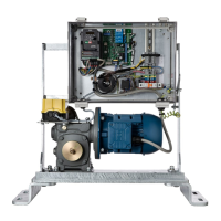
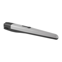
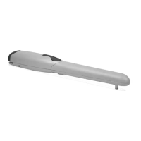
The product is an electromechanical gear motor, equipped with a 24 v high
duty cycle electric motor and worm drive.
The gear motor is powered by the external control unit to which it is
connected. In the event of a black out, it is possible to move the gate leaves
by hand, by manually releasing the gear motor.
3
INSTALLATION
3.1 - Checks before installation
B
efore installation, check the integrity of the components, suitability of the
model chosen and suitability of the environment chosen for the installation.
IMPORTANT – The gear motor cannot automate a manual gate which
does not have a safe and efficient mechanical structure. Furthermore,
it cannot solve the faults caused by wrong installation or bad mainte-
nance of the gate itself.
3.2 - Suitability of the gate to being automated
• Check the mechanical structure of the gate is suited to being automated
and conforms to the national laws in force (if necessary make reference to
the da-ta on the gate label).
• Moving the gate leaf manually in Open and Close position, check the
move-ment occurs with equal and constant attrition at each point of the
stroke (there must be no moments of greater effort).
• Check the gate leaf remains balanced, that it does not move if brought
man-ually to any position and left stopped.
• Check the space around the gear motor allows to manually unblock the
gate leaf, easily and safely.
• Check the surfaces chosen for installing the product are solid and can
guar-antee stable fixing.
• Check the gate is no more than 68mm from the back of the post it is hung
from otherwise it will not work.
d
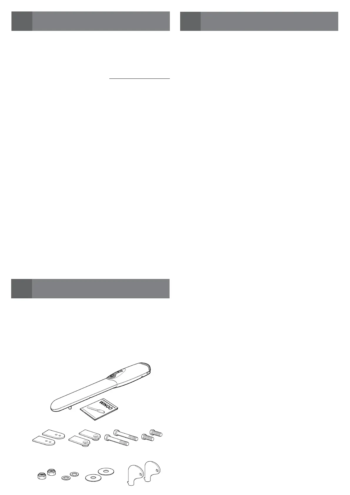
e
electromechanical gear motor (2x)
Tongues and hardware for gate mounting brackets and keys to
manually release gear motor
Printed copy of the
instruction manual
3.3 - Limits of Gate Leaf Size and Weight
Before installing make sure the gate isn't too large or heavy for the
gear motor. For gates clad with metal sheeting, timber palings,
aluminium slats or hardwood battens with small gaps between them
then each gate leaf should be no wider or higher than 2m. If the gate has
aluminium slats, hardwood battens or timber palings that are widely
spaced then the gate can be as wide as 2.4m but no higher than 1.2m or
if its made from aluminium tubing or steel wire that lets wind blow
through then each leaf can be as wide as 2.6m and no higher than 1.2m.
3.4 - Preparing for installation
Fig. 1 shows an example of an automation sy
stem designed with Nice
com-ponents. These components are positioned according to a typical and
usual
scheme.
Making reference to fig. 1, decide the approximate position in which to
install each component envisaged by the system and the most appropriate
connec-
tion diagram.
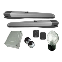
Useful components for producing a complete system (fig. 3):
A - Electromechanical gear motors
B - Couple of photocells
C - Couple of stop blocks (in Opening)
D - Columns for photocells
E - Flashing signaling device with incorporated antenna
F - Key selector switch or digital keypad
G - Control unit
3.5 - Installation the mounting brackets and gear motor
There are three sets of mounting brackets available for the gear motor, which
depend of the position of the gate relative to the post, the size of the post and
whether the gate is opening inwards or outwards.
Fig.3, 4 and 5 show how the different mounting brackets that apply to different
gates, hinges and posts. These Brackets can be purchased from Grant's
Automation www.grantsautomation.com.au.
If you can't find a bracket that suits your gate you can either make your own
with reference to those in this manual and information on Grant's Automations
website or get Grant's Automation to design and make it for you.The Post
Mounting Bracket (PMB) is fitted first with the height being determined by the
gate rail the Gate Mounting Bracket (GMB) is fitted to. Refer Fig.6. Then the
motor must be fitted to the PMB (Fig.7) and connected to the gate controls
(Fig.8). The controls are then powered up and used to drive the motor to its
closed position, with the Gate Mounting Bracket fitted (Fig.9) find the location
on the gate and fit the Gate Mounting Bracket. With the motor in manual
release the open hard stop can now be set to set the open position of the
gate (Fig.2).
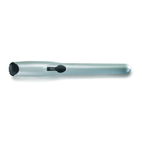
3.6 - Setting the built in hard stop
The built in hard stop allows the stop position of the gate leaf to
be set without using mechanical stops on the gate itself. Fig.2 shows how to
do this.
 Loading...