Do you have a question about the Nice 4024 and is the answer not in the manual?
Crucial instructions for personal safety during operation and handling of the automation system.
Essential guidelines and precautions to follow before and during the installation process.
Key checks to ensure suitability and safety before starting the installation process for the gate automation.
Criteria to verify if the gate structure is appropriate for automation, checking movement and balance.
Specifies the maximum dimensions and weight for gate leaves compatible with the gear motor.
Guidance on planning the automation system layout and component positioning according to typical schemes.
Detailed steps and considerations for mounting the gear motor and associated brackets for gate automation.
Instructions on how to set the gate's open or closed position using the built-in mechanism.
Procedures for checking the functionality and safety of the automation system components.
Steps to follow after inspection to make the automation ready for use, ensuring all checks are positive.
Details on required maintenance tasks and frequency to ensure consistent safety and maximum life.
Step-by-step guide on how to manually release and operate the gear motor during power failures or anomalies.
This document describes the Nice 4024 Kit and 5024 Kit, which are electromechanical swing gate operators designed for residential use. The manual provides comprehensive instructions and warnings for installation, use, and maintenance, emphasizing safety and proper operation.
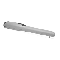
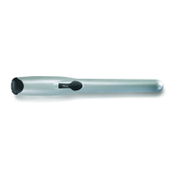
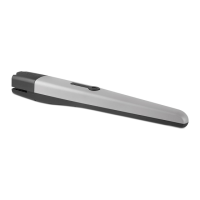
The Nice 4024 Kit and 5024 Kit are swing gate operators that automate the opening and closing of gates. These devices are electromechanical gear motors, each equipped with a 24V high-duty cycle electric motor and a worm drive. They are powered by an external control unit. The system is designed to provide a high level of safety, preventing movement in the presence of people or objects through detection systems, and ensuring predictable and safe activation.
The gear motor includes a built-in hard stop mechanism, allowing the gate's stop position to be set without requiring external mechanical stops. This feature enhances installation flexibility and simplifies the setup process. In the event of a power outage or system anomaly, the gate can be manually operated by releasing the gear motor. This manual release mechanism ensures that the gate can always be opened or closed, even when electrical power is unavailable or if there is a system malfunction.
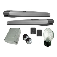
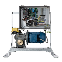
The system can be integrated with various components to create a complete automation setup, including photocells, stop blocks, flashing signaling devices with incorporated antennas, and key selector switches or digital keypads. These components work together to ensure the gate operates safely and efficiently. The control unit manages the overall operation, including motor direction, phase shift in leaf movement, and limit switch settings.
Before installation, it is crucial to verify the gate's suitability for automation, ensuring its mechanical structure is safe and conforms to national laws. The gate leaves should move with equal and constant attrition throughout their stroke, remain balanced, and not move when manually stopped. Sufficient space around the gear motor must be available for safe and easy manual unblocking. The gate should not be more than 68mm from the back of the post it is hung from, otherwise it will not work.
The manual provides detailed instructions for preparing the installation, including deciding the approximate position for each component and connecting them according to the appropriate diagram. Three sets of mounting brackets are available, depending on the gate's position relative to the post, post size, and whether the gate opens inwards or outwards. These brackets are designed to accommodate various gate and post configurations, with options for flush-mounted hinges and different offsets. Custom brackets can also be designed if standard options are not suitable.
Once the mounting brackets and gear motor are fitted, the motor is connected to the gate controls. The controls are then used to drive the motor to its closed position. The built-in hard stop can then be adjusted to set the open position of the gate. For outward-opening gates, it is necessary to move the built-in hard stop to the other end of the motor and reverse the motor wires.
The system includes safety features such as a disconnection device in the power supply to ensure full disconnection during maintenance. All installation and maintenance operations must be performed with the automation disconnected from the electrical power supply. If the gate is fitted with a pedestrian door, a control system must be included to prevent motor operation when the pedestrian door is open. Push-button controls should be positioned in sight of the automation, away from moving parts, at a minimum height of 1.5m from the ground, and inaccessible to the public.
In case of anomalous behavior, users are instructed to cut off power to the system and manually unblock it. Repair work should only be performed by a trusted fitter. The system can still function as an unautomated opening once the gear motor is unblocked.
Regular maintenance is essential to ensure the safety and longevity of the automation system. Maintenance should be performed in accordance with the safety instructions in the manual and applicable laws and regulations. For the gear motor, programmed maintenance is required at least every six months for normal domestic use, though this period may vary depending on the intensity of use. All maintenance and repair work must be performed by qualified personnel and documented.
Maintenance operations include:
Users are advised not to modify the system or adjust programming parameters themselves, as this is the responsibility of the fitter. The only maintenance task recommended for users is cleaning the photocell glass and removing any leaves or stones that might obstruct the automation. Before cleaning, the automation should be unblocked, and cleaning should be done with a slightly dampened sponge.
At the end of the automation's life, it must be dismantled by qualified personnel, and materials should be recycled or disposed of according to local regulations. The manual also provides guidance on calculating the estimated durability of the product based on a demand index, which considers factors like leaf weight, leaf length, operating temperature, blind leaf presence, and installation in windy areas. This helps in planning for the system's lifespan and maintenance schedule.
| Model | Nice 4024 |
|---|---|
| Type | Electromechanical gear motor |
| Motor voltage | 24 V DC |
| Operating temperature | -20°C to +50°C |
| Protection level | IP44 |
| Max. weight | 300 kg |
| Housing Material | Aluminium |
| Power supply | 230V AC |