4
ELECTRICAL CONNECTIONS
CAUTION!
– A wrong connection can cause faults or danger; therefore follow
scrupulously the connections set out.
– Perform the connection operations when the electricity is off.
To connect the gear motor to the control unit, proceed as follows:
01. Remove the lid of the gear motor as shown in fig. 12;
02. Slacken the gearmotor cable clamp, thread the connecting cable through
the hole and connect the three electric wires as shown in fig. 13;
03. Replace lid on gear motor.
To check the connections, direction of rotation of the motor, phase shift in the
movement of the leaves and setting the limit switch, refer to the instructions
manual of the control unit.
IMPORTANT – With a gate configured with opening towards the outside invert
the power supply wires with respect to the standard installation.
5
INSPECTING THE AUTOMATION
This is the most important phase in realising the automation to guarantee maxi-
mum safety. The inspection can be used also to periodically check the devices
which make up the automatism.
The inspection of the entire system must be performed by expert and
qualified staff who must take responsibility of the tests requested, depending
on the risk involved and to check compliance of what is set out by laws, rules
and regulations and in particular all the requirements of regulation EN 12445
which establishes the testing methods to verify gate automatisms.
Inspection
Each single component of the automatism, for example sensitive edges, pho-
tocells, emergency shutdowns, etc. requires a specific inspection phase; for
these devices follow the procedures shown in the respective instruction manu-
als. For inspection of the gear motor follow the operations below:
01. Check that everything in this manual and in particular in chapter 1 has
been rigorously complied with;
02. Unblock the gear motor as shown in fig. 14;
03. Check it is possible to manually move the leaf when opening and closing
with a force no greater than 390N (approx. 40 kg);
04. Block the gear motor and connect the electrical power supply;
05. Using the control or shutdown devices envisaged (key selector switch,
control buttons or radio transmitters), perform a number of opening, clos-
ing and stopping tests of the gate and check it behaves as it should;
06. Check the correct operation of all the safety devices one by one in the sys-
tem (photocells, sensitive edges, emergency shutdown, etc.) and check
the gate behaves as it should;
07. Command a closing manoeuvre and check the force of the impact of the
leaf against the end of the mechanical limit switch. If necessary, try to un-
load the pressure, finding a setting which gives better results;
08. If the dangerous situations caused by the movement of the leaf have been
protected by limiting the force of impact the force must be measured as re-
quired by regulation EN 12445;
Note – The gear motor is not provided with torque setting devices, such regu-
lations are done by the Control unit.
Putting into operation
This can occur only after having performed, with positive results, all the inspec-
tion phases of the gear motor and other devices present. To put it into opera-
tion refer to the instructions manual of the control unit.
IMPORTANT – It is forbidden to put into partial or provisional operation.
6
PRODUCT MAINTENANCE
To keep the level of safety consistent and to guarantee maximum life of the en-
tire automation it is necessary to maintain it regularly.
The
maintenance must be performed in line with the safety instructions of this
manual and according to what is set out by the laws and regulations in force.
For the gear motor a programmed maintenance within no more than 6 months
is required.
Maintenance operations:
01.
02.
Disconnect any sources of electricity.
Check the status of deterioration of all the materials which make up
the automation with particular attention to signs of erosion or
oxidation of the structural parts: replace the parts which do not
provide sufficient guar
antees.
3. Check the screw connections are sufficiently tight.
4. Check the bolt and worm drive are suitably greased.
5. Check the wear of the moving parts and, if necessary, replace used
parts.
6. Reconnect the sources of electrical power and perform all the tests
and checks envisaged in chapter 5.
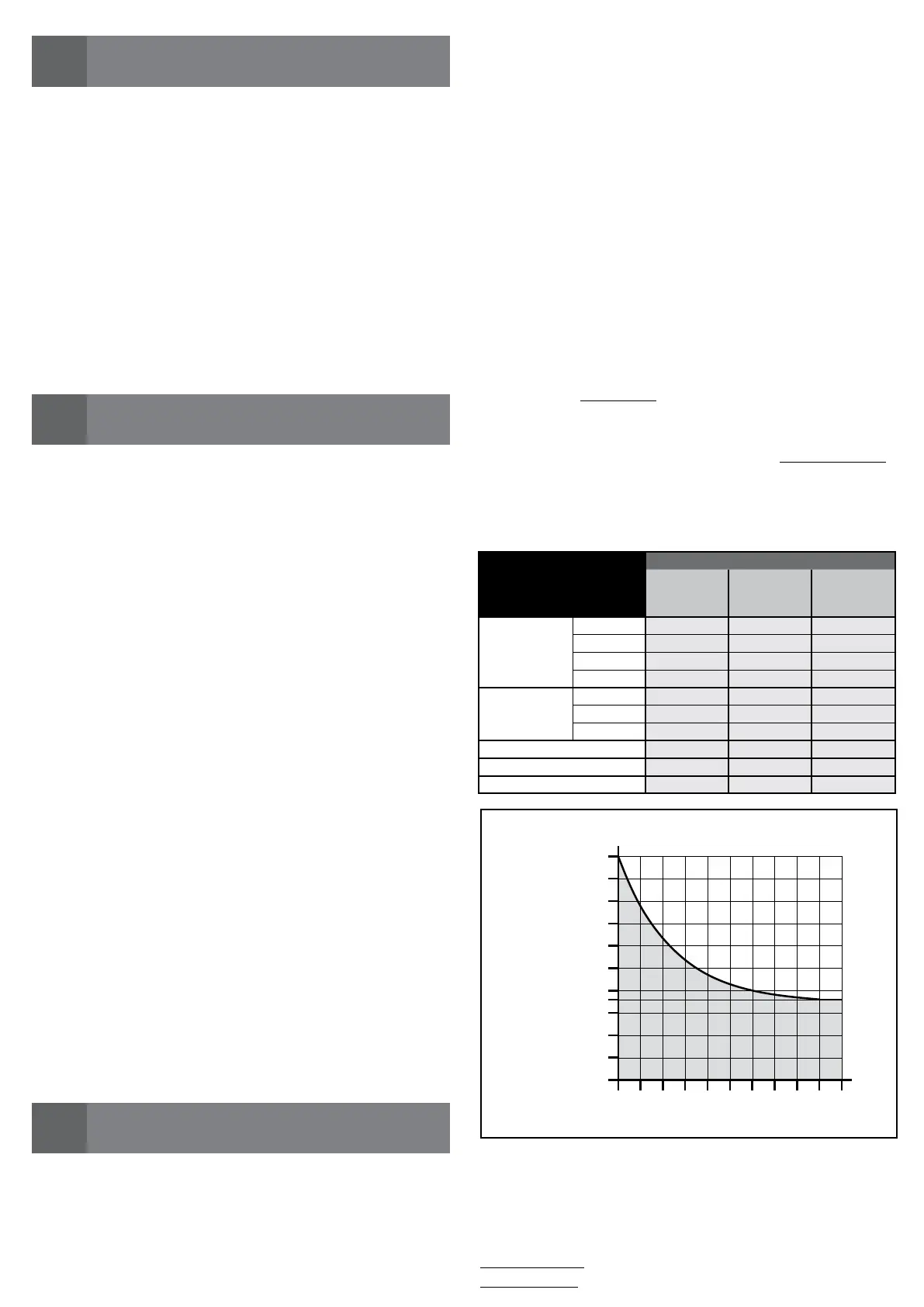
0
0
25.000
50.000
75.000
100.000
125.000
10 20 30 40 50 60 70 80 90 100
GRAPH A
Demand index (%)
cycles of manoeuvres
Example of calculation of durability of a Wingo WG5024 gear motor (re-
fer to Table 2 and Graph A):
- leaf weight = 200 kg (demand index= 10%)
- leaf length = 2.5 m (demand index = 20%)
- no other stress elements present
Total demand index = 20%
Durability estimate = 80.000 cycles of manoeuvre
Durability of the product
Durability is the average economic life of the product. The value of durability is
strongly influenced by the demand index of the manoeuvres performed by the
automatism: that is the sum of all the factors which contribute to the wear of
the product (see Table 2).
To establish the probable durability of your automatism proceed as follows:
01. Calculate the demand index summing the values in percentage of the en-
tries present in Table 2 to each other;
02. In Graph A, from the value just found, trace a vertical line until you inter-
sect the curve; from this point trace a horizontal line to cross the line of “cy-
cles of manoeuvres”. The value established is the estimated durability of
your product.
T
he estimate of durability is performed on the basis of the design calculations
and the results of tests carried out on prototypes. In fact, being an estimate, it
does not give any guarantee on the actual duration of the product.
TABLE 2
Demand index
WG4024
WG4000
WG4000/V1
WG5024
WG5000
WG5000/V1
WG3524HS
Leaf weight:
> 100 kg 10 % 0 % 10 %
> 200 kg 20 % 10 % 20 %
> 300 kg 30 % 20 % –––
> 400 kg ––– 30 % –––
Leaf length:
1 - 2 m 20 % 0 % 10 %
2 - 3 m ––– 10 % 20 %
3 - 3,5 m ––– 20 % –––
Operating temperature: 20 % 20 % 20 %
Blind leaf: 15 % 15 % 15 %
Installation in windy area: 15 % 15 % 15 %
 Loading...