CBOX1050
Installation and Programming Manual
2020
support.hysecurity.com
CONNECT BLUEBUS PHOTO EYES TO BOARD
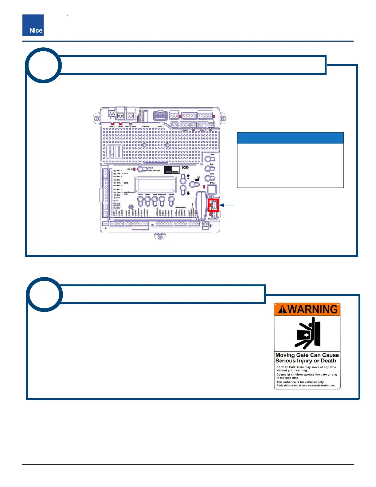
IMAGE 6-1: BLUEBUS CONNECTOR LOCATION
Install through beam photo eye bus wires (no polarity) into 2-pin BlueBUS connector on control board (IMAGE
6-1). If an alternative photo eye is used, follow installation instructions included in the kit.
6
1. Place one warning sign (IMAGE 7-1) on outside of gate and the other
inside of gate in high visibility locations (eye height) to warn of entrapment
dangers. If signs cannot be attached to gate, ensure they are as visible as
possible to pedestrians and anyone operating the gate.
2. Use two tie wraps per sign, or alternative means, to securely ax signs to
gate.
7
ATTACH WARNING SIGNS TO GATE
IMAGE 7-1: GATE ENTRAPMENT WARNING SIGN
BLUEBUS
CONNECTOR
IMPORTANT!
If using the model EPMB/A non-
adjustable photo eye (H), Do not
attempt to jumper or short the
BlueBus connector pins as this
will damage the control board.