CBOX1050
Installation and Programming Manual
1919
MX4682 Rev. D ©2021
K
I
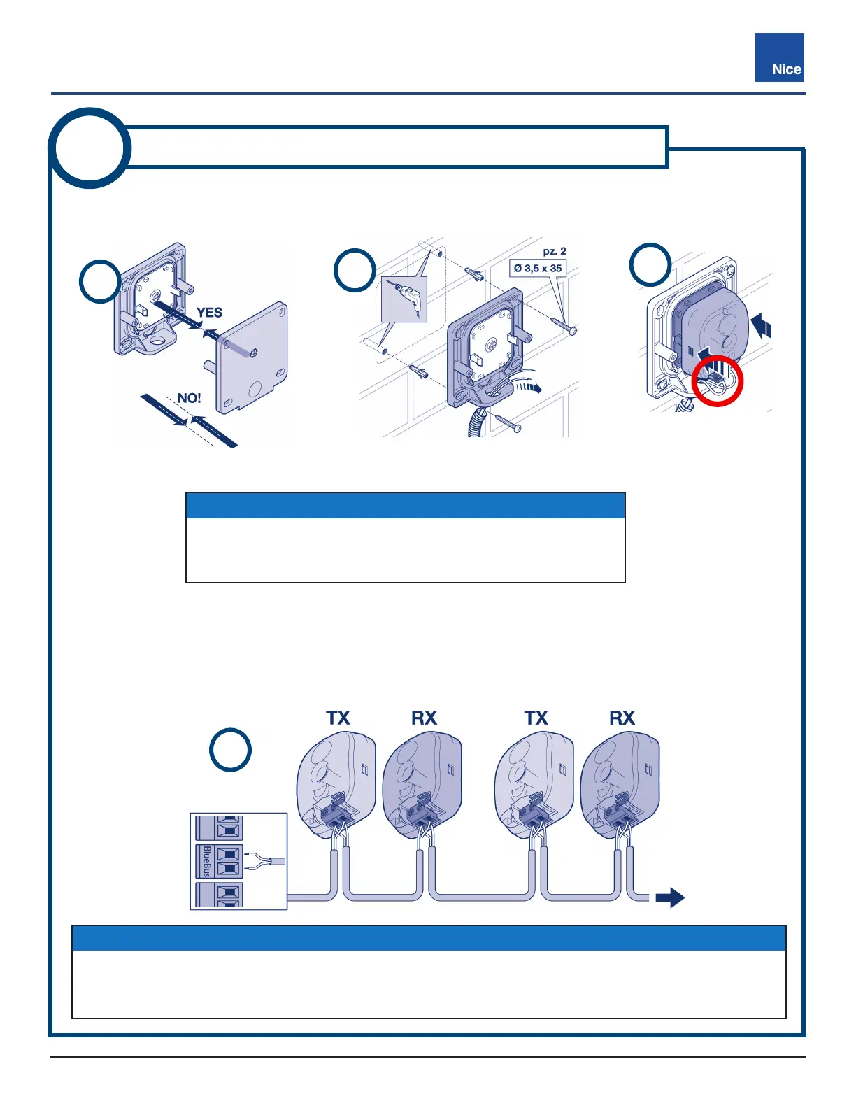
1. Ensure alignment between receiver and transmitter brackets (H), then ax both to selected locations
with included screws (I).
2. Thread 2-conductor jacketed cable through bracket hole and snap photo eye assembly (J) into bracket.
3. Install wires into screw terminals (J, red circle) in parallel as shown (K). No polarity required.
J
H
5
INSTALL & WIRE BLUEBUS PHOTO EYES
IMPORTANT!
If using the model EPMB/A non-adjustable photo eye (H),
ensure the mounting surfaces for both devices are parallel with
each other to ensure accurate alignment between TX and RX.
NOTICE
’ Maximum total length of wire should not exceed 165 feet (50 meters).
’ When replacing photo eyes, jumper setting on the new device must match the old device to avoid
having to re-learn the BlueBUS configuration.