CBOX1050
Installation and Programming Manual
5858
support.hysecurity.com
GUARD STATION INPUTS
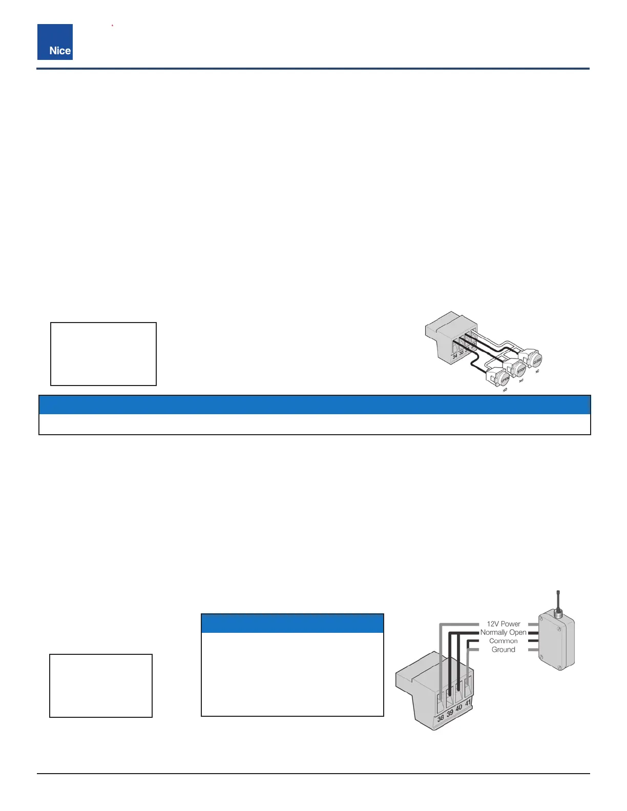
WIRING (EXAMPLE)
PIN 38 = 12V
PIN 39 = OPEN
PIN 40 = CLOSE
PIN 41 = GND
PIN 34 = OPEN
PIN 35 = STOP
PIN 36 = CLOSE
PIN 37 = GND
RADIO INPUTS
WIRING (EXAMPLE)
GUARD STATION INPUT (34-37):
• With the Guard Station switches installed, the user can operate the gate by pushing the respective buttons
for the command that is desired.
• Gate Open and Close are controlled by NORMALLY OPEN (NO) and Stop is controlled by NORMALLY
CLOSED (NC) momentary switches.
• OPEN: (34) Dry contact input for a guard station open switch. Momentarily shorting the Open input (34) to
GND opens the gate to the full open position with the subsequent auto-close feature enabled.
• STOP: (35) Dry contact input (Normally Closed) for a guard station stop switch. Momentarily opening the
Stop input (35) stops the opening gate at its current position. While this input is activated, all other inputs are
disabled and are not functional.
• CLOSE: (36) Dry contact input for a guard station close switch. Momentarily shorting the Close input (36) to
GND closes the gate (primary and secondary).
• The FAIL SAFE connector which is shorted at the factory with a jumper (pins 35 & 37, Normally Closed NC),
may be wired in parallel with the Fire input to release the motor in the event of an emergency entry by the fire
department during a power failure.
RADIO INPUTS (38-41):
• Customer supplied radio receiver can enable the gate operator to be operated via remote (wireless key-card
readers or user remote controls).
• Open (39) is a dry contact input for an accessory radio open switch. Momentarily shorting the Open input (39)
to GND (41) opens the gate to the full open position with the subsequent auto-close feature enabled.
• Close (40) is a dry contact input for an accessory radio close switch. Momentarily shorting the Close input (40)
to GND (41) closes the gate.
• Connecting the Open (39) and Close (40) pins together with the relay of a receiver enables step by step gate
control. This configuration allows a single button to control the gate in the following sequence:
a) 1st Press = Gate Open
b) 2nd Press = Gate Stop
c) 3rd Press = Gate Close
d) 4th Press = Gate Stop
PRIMARY/SECONDARY LINK CONNECTOR (38-41):
The Primary/Seconary control board as a secondary.
NOTICE
12VDC Power (PIN 38) is OFF
when board enters Standby Mode.
Power for external radio receivers
should be sourced from Pin 11
in a solar application when the
Standby mode is turned on.
NOTICE
If the guard station inputs are not used, STOP (35) and GND (37) need to be tied together.