ENGLISH – 5
TECHNICAL SPECIFICATIONS OF ELECTRICAL CABLES
Identication
no.
Cable characteristics
f
MOTOR POWER SUPPLY cable
1 cable 3 x 1.5 mm
2
Maximum length 10 m [note 4]
g
ELECTRIC LOCK CONNECTION cable
1 cable 2 x 1 mm
2
Maximum length 10 m
h
ENCODER CONNECTION cable
1 cable 2 x 1 mm
2
Maximum length 10 m [note 4]
Note 1 If the power supply cable is longer than 30 m, a cable
with larger cross-sectional area (3 x 2.5 mm
2
) must be
used and a safety earthing system must be installed
near the automation.
Note 2 If the BlueBus cable is longer than 20 m, up to maximum
40 m, a cable with larger gauge (2 x 1 mm
2
) must be
used.
Note 3 These two cables can be replaced by a single 4 x 0.5
mm
2
cable.
Note 4 These cables can be replaced by a single 5 x 1.5 mm
2
cable.
a
The cables used must be suited to the type of envi-
ronment of the installation site.
a
When laying the ducting for routing the electrical
cables and for the cable entry point into the control
unit housing, check that there are no water depos-
its in the junction wells nor condensate in the con-
nection ducts, as water and damp conditions could
damage the product’s electronic circuits.
3.5 INSTALLING THE CONTROL UNIT
a
Secure the control unit to an unmovable, vertical,
at surface adequately protected against possible
impacts. The lower part of the control unit must be
at least 40 cm above the ground.
l
The control unit is also suitable for being installed
outdoors, as it is supplied in a container that, if ad-
equately installed, guarantees an IP54 protection
rating.
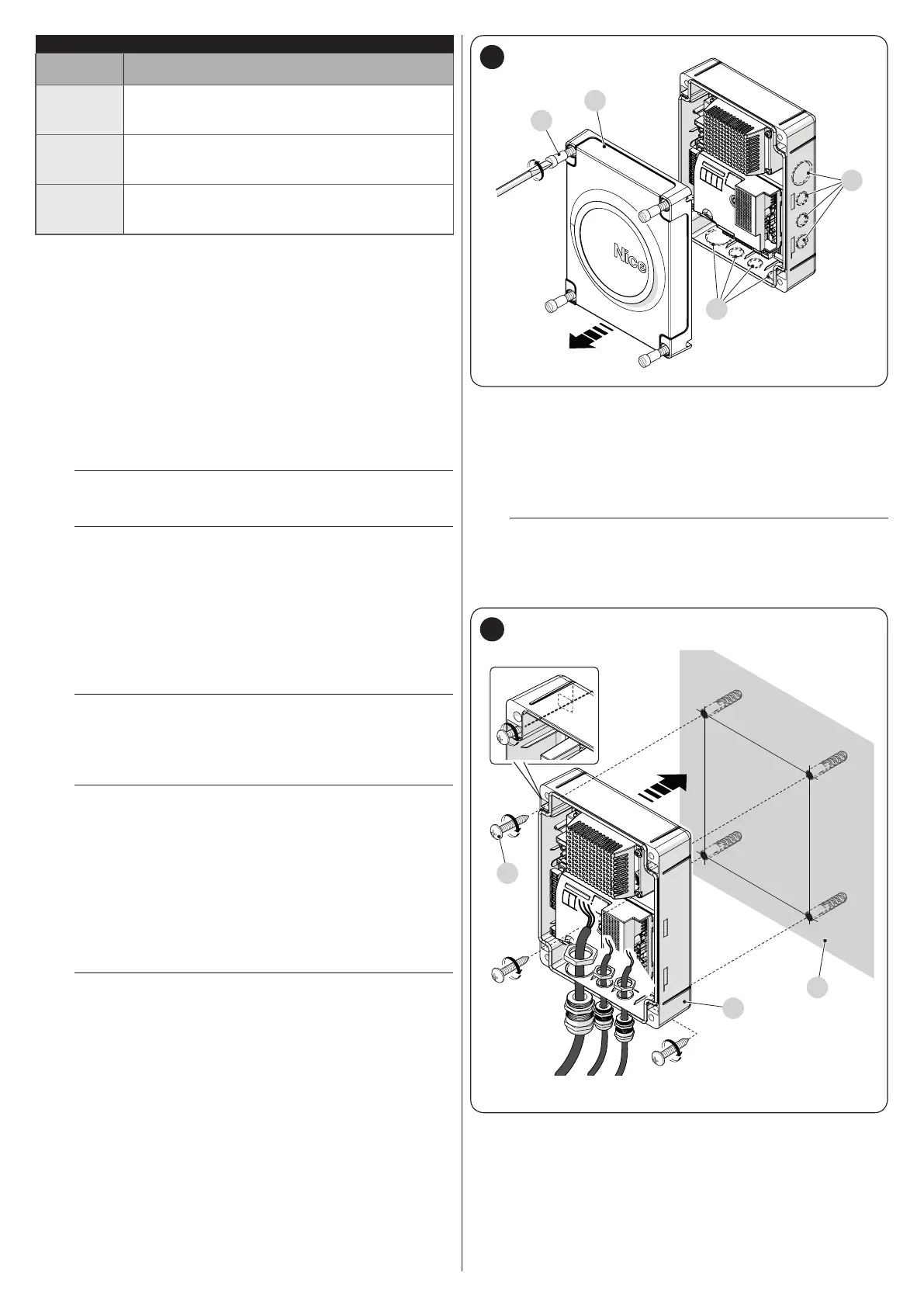
To secure the control unit (“Figure 5” and “Figure 6”):
1. loosen the screws (A) and remove the cover (B) of the
control unit
2. identify the pre-cut holes (C) located along the lower side
of the box and perforate the ones used to pass the elec-
trical cables
l
The side cable entry (D) can only be used if the con-
trol unit is installed indoors, in a protected environ-
ment.
B
D
A
C
5
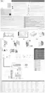
3. drill the wall (E) by observing the measurements shown in
the gure and arrange suitable wall plugs (not supplied)
4. position the box (F) and fasten it with the screws (G) (not
supplied)
5. arrange cable glands for passing the connecting cables
6. make the electrical connections by operating as de-
scribed in the “ELECTRICAL CONNECTIONS” chapter.
l
To install any other devices used on the automated
system, refer to the respective instruction manuals.
7. after making the electrical connections, put the cover (B)
back on and tighten the screws (A).
205 mm
237 mm
E
G
F
6