ENGLISH – 9
CloseOpenSbSStop
Bluebus
1 2 3 4 5 6 7 8 9
10 11 12
L1
L2
S
11
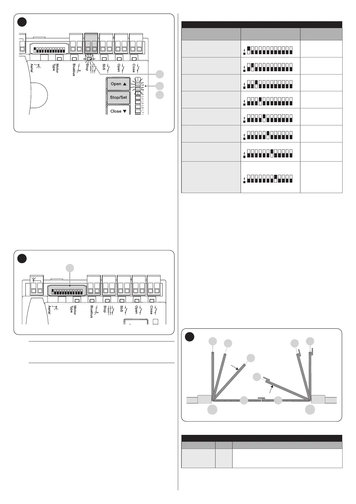
LEDs “L1” and “L2” on the control unit (“Figure 11”) emit some
slow ashes to signal that the learning procedure must be car-
ried out.
To do this:
1. simultaneously press and hold the
f
and
g
buttons
2. release the buttons when LEDs “L1” and “L2” start ash-
ing quickly (after roughly 3 seconds)
3. wait a few seconds until the control unit has completed the
device learning phase
4. once this phase terminates, the “Stop” (S) LED must be lit
and LEDs “L1” and “L2” must switch off (LEDs “L3” and
“L4” could start ashing).
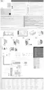
4.7 MOTOR SELECTOR
The control unit is equipped with a selector (A - “Figure 12”) that
allows for specifying which type of motor to use (see “Table 4”).
CloseOpenSbSStop
Bluebus
1 2 3 4 5 6 7 8 9
10 11 12
A
12
m
The motor selector must be set before activating
the mechanical stop learning function.
m
Any conguration not appearing in “Table 4” is not
allowed.
Table 4
SELECTING THE MOTOR TYPE
Motor type Motor selector
Visualisation on
Oview
MB4024 - MB5024 -
HY7024 - HY7124
O
N
MB4024
MFAB3024
O
N
ME3024
TO4024 - XFAB2124 -
LFAB4024
O
N
TO4024
TO5024 - TO5024I
O
N
TO5024
TO7024 - TO6024HS
O
N
TO7024
BFAB5024
O
N
BM5024
METROELITE
- MFAB3024HS -
TO5024HS
O
N
METROE
WINGOELITE
- WG3524HS -
LFAB4024HS
- TTN3724HS -
TTN6024HS
O
N
WINGOE
4.8 LEARNING OF THE MECHANICAL STOP
POSITIONS
Once the connected devices have been learned, the mechan-
ical stop positions must be learned (maximum opening and
maximum closing). This procedure can be carried out in three
different ways: automatic, manual and mixed.
In automatic mode, the control unit learns the mechanical stops,
calculates the most appropriate gate leaf offsets and calculates
the slowdown points “SA” and “SC” (“Figure 13“).
In the manual mode, the positions (“Figure 13”) are programmed
one by one, by shifting the leaves to the desired points. The po-
sition to be programmed can be identied when one of the eight
LEDs “L1...L8” ashes (see “Table 5“).
In the mixed mode, it is possible to perform the automatic pro-
cedure and then, with the manual procedure, modify one or
more positions with the exception of the “0” and “1” positions,
which correspond to the mechanical stop positions.
1 1
M1 M2
0 0
SC
SA
A
A
13
Table 5
PROGRAMMING POSITIONS
Position LED Description
Position 0
(motor 1)
L1
maximum closing position: when the leaf
relative to motor 1 strikes the closing
mechanical stop