8
3.2.2) SNA11 guide assembling
The guide SNA11 guide is already assembled. The only operation
required is tensioning the belt by means of the M8 nut (H), as shown
in figure 17, until it is sufficiently taut.
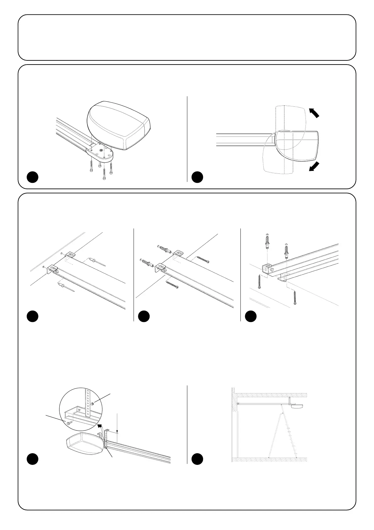
3.2.3) Mounting the gearmotor to the guide
1. Join the SPIN gearmotor with the guide head (B); then secure by means of the four V6.3x38, screws, as shown in figure 18.
2. The motor can be rotated in three different positions, as shown in figure 19.
18 19
3.2.4) Fissaggio del motoriduttore al soffitto
1. On the basis of distances A and B in figure 5, trace the two fixing points of the front guide bracket at the centre of the door. On the basis
of the type of support surface, the front bracket can be fixed with rivets, plugs or screws (figures 20, 21). If distances A, and B (figure 5)
are sufficient, the bracket can be fixed directly onto the ceiling, as shown in figure 22.
2. After drilling the holes in the relative points, leaving the gearmotor on the ground, lift the guide from the front section and secure by means
of two screws, plugs or rivets, according to the installation surface.
3. Secure the brackets (I) by means of the M6x15 screws (L) and nuts M6 (M) selecting the hole most suited to ensure distance B, as shown
in figure 23.
4. Using a ladder, lift the gearmotor until the brackets are touching the ceiling. Trace the drilling points and then return the gearmotor to the
ground, as shown in figure 24.
20 21 22
23 24
L
M
I
B