4 – English
EN
Connection of direct safety switches
The safety elements that directly intervene in the control process are
connectedtoterminalJ10ofterminalblockX2.Theemergencystop
or safety line attachment, anti-entrapment safety device and safety
deviceforthewicketdoorarebetweenthem.
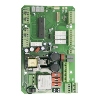
Connection of safety switch for wicket door (g.8)
ThesafetyswitchistobeconnectedtoterminalJ10terminalofter-
minalblockX2inthedoorswithbuiltinservicewicketdoor.
Attention! Remove the jumper on J10, if present.
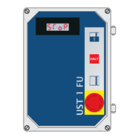
Connection of the control transmitter for switch with
cable connected to the ceiling (g.8)
IntheUST1Kcontrolunititispossibletoconnectaswitchwithcable
connectedtotheceiling,activatedusingtraction(NCcontact)toter-
minalJ17ofterminalblockX4;thefunctionofthisinputcorresponds
totheCLOSESTOPOPENSTOPstepbystepcontrol.
B2B1
W
V
J11
J10
Cable slackening /spring
breakage safety or
anti-unwinding safety
switch
U
X2
8
9
Traction
switch
1 3 5 72 4 6 8
STOP OPEN Impulse CLOSE
X4
J15 J16 J17 J18
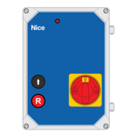
Connection of the remote control (radio module)
ItispossibletoconnecttheNiceOXIorOXIFMreceiveroftheOPE-
RAseriestothe10PINslot(J38).
To this regard, it is necessarythatthesidewiththeprogramming/
LEDbuttonfacestheinternalsideofthehousing.
ItisnecessarytosetthespecicparametersontheK5moduleifthe
OXIradiosystemisused!
For more details, see the instructions for using the receiver, manual
transmitter and K5 module.
OXI/OXIFM
Jumpers and U-bolts necessary for control unit operation
with components not connected
Jumpers: Ubolts:
X2J10 X8Pin56
X4J15 X9Pin12
X5J31 8.2kΩPin12
X6J33 OptoPin23
AdditionalelectroniclimitswitxhX7J26,J27,J28
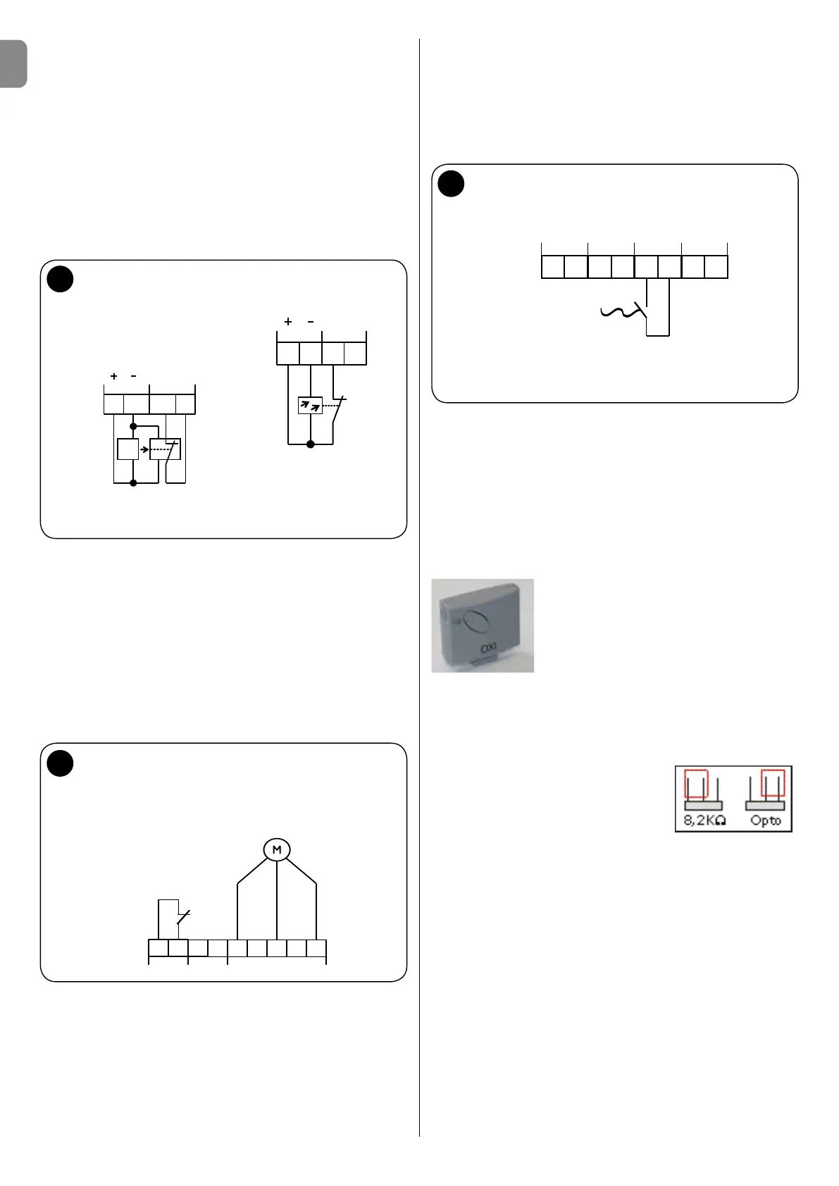
Connecting photoelectric barriers/pairs of photocells
(g. 6 a + b)
ItispossibletodirectlyconnectaphotoelectricbarriertotheUST1K
controlunit(toterminalblockX5)tomakethepassagesafe.Ifthe
infraredbeamofthephotoelectricbarrierisinterruptedduringthe
CLOSINGmovementofthedoor,itblocksandreversesthedirection
towardtheuppernalposition.
ATTENTION:
Theswitchingcontactandthepositivesideoftheelectronicbarrier
systemareconnectedtoterminalJ30/1withpositivepotentialina
onewayphotoelectricbarrierwithonlythreeconnectionpoints.
RemovethejumperfromterminalJ31ofterminalblockX5ifthephoto-
electricbarrierisconnected.
7
a
b
21
3 4
J30
S
Photo
J31
E
S=transmitter
E=receiver
Transmitter and receiver
photoelectric barrier connection
X5
Safety
photoelectric
barrier
24V DC voltage
power supply
Contact
(opening)
21
3 4
J30
Photo
J31
X5
Reflection photoelectric
barrier connection