EN
English – 5
Motor cable conguration
Mechanical limit switches
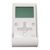
rotoMWire Control station
U1U/11J - 2X
V2V/11J - 2X
W3W/11J - 2X
-Jumper01J - 2X
X7 - J29 Grey
X7 - J34/B Green
X7 - J35/- White
X7 - J34/A Pink
X7 - J29 Yellow
X7 - J35/+ Brown
AMP plug
AMP plug
AMP plug
AMP plug
AMP plug
AMP plug
MECHANICAL LIMIT SWITCH SETTING
Mechanical limit switch setting
Attention!Theprocedureforsettingthelimitswitchesisexplainedon
the56pagesthatfollow.
Thestoppositions withdoorinthe up/downpositionaredened
with setting the limit switches.
Themotormustbeelectricallyconnectedformakingthissetting.
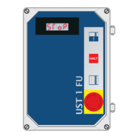
Thelimitswitchboard(g.11limitswitchboardwith8cams)is
accessibleoncethelimitswitchguardisunscrewed.
Ifexternalcontroldevicesarenotyet connected, itis possible to
controlthe door with the controlunit usingthe integratedOPEN,
CLOSEandSTOPbuttonsindeadmanmode.
IftheOPENbuttonispressed,thedoorshouldopen;otherwisethe
L1andL2phasesonthecontrolunitmustbereversedafterhaving
madesurethevoltagehasbeencutoff.
Ifthegearmotorwasinstalledturned180°(upsidedownassembly),
thedoormustalsoopenwiththeintegratedOPENbutton;otherwise
theL1andL2phasesmustbereversedinzerovoltageconditions.
It is also necessary to correct the two emergency stop limit switches
so they trip after the limit switch.
Determining the lower position of the door
To set the limit switches for the lower position of the door, perform
thefollowingoperations(g. 11):
MovethedoortothedesiredCLOSEposition.
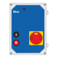
Set the contact cam 3 Ei (white)sothelimitswitchisenabled.
8 white Additional limit switch 2 CLOSING
7 green Additional limit switch 2 OPENING
6 white Additional limit switch 1 CLOSING
5 green Additional limit switch 1 OPENING
4 red Safety limit switch CLOSING
3 white Limit switch CLOSING
2 red Safety limit switch OPENING
1 green Limit switch OPENING
Mechanical limit switch setting
Small motors - 8 contact cams
Mechanical limit switch setting
Large motors - 7 contact cams
7 white Additional limit switch 2 CLOSING
6 green Additional limit switch 2 OPENING
5 white Additional limit switch 1 CLOSING
4 red Safety limit switch CLOSING
3 white Limit switch CLOSING
2 red Safety limit switch OPENING
1 green Limit switch OPENING
Optional
B A
}
}
11
Mechanical limit switches
TightenthexingscrewA.
To get accurate adjustment, use the screw B.
MovethedoorintothedesiredOPENINGposition.
Set the contact cam 1 Eh(green)sothelimitswitchisenabled.
TightenthexingscrewA.
To get accurate adjustment, use the screw B .
The safety limit switches 2 SEi and 4 SEh(red)mustbesetsothey
intervene right after the control limit switch is passed.
The safety limit switches 2 SEi and 4 SEh(red)arefactorysetso
they follow the limit switch at a short distance.
Checkthecorrectpositionofthexingscrewsaftertheoperation
test.
The additional limit switches 8 P2i and 7 P2h are closing contacts
with zero potential, and the additional limit switches 6 P1i and 5
P1h are switching contacts with zero potential.
In automatic mode the limit switch 6 is used as a preliminary limit
switch.Therefore,itistobesetsothatittripswhenthedoorreaches
adistanceof5cmfromtheground.
In deadman mode it is not necessary to set it and it is used as a
contactwithzeropotential!
10
Small types Large types
Optional