6 – English
EN
08. After the inspection, fix each single wireless device to the preestablished
points (refer to figs. 7, 8, 9). Fix the WM100 interface in proximity to the control
unit or inside it and protect it adequately (fig. 10). Finally, use the double stick
tape included in the supply to fasten the antenna in the position established
during the inspection.
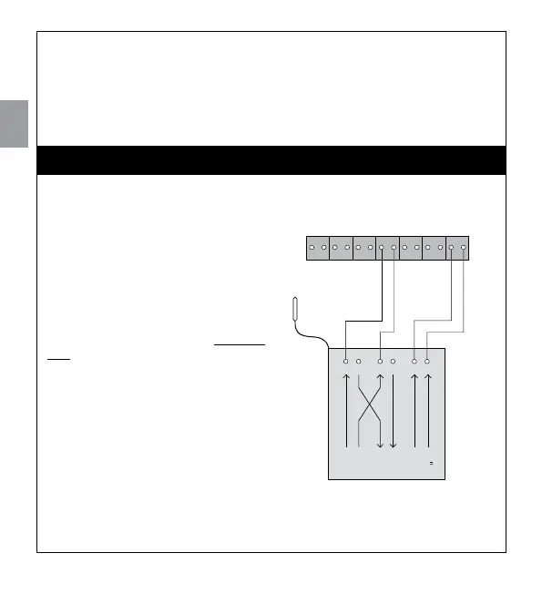
4.1 - Connecting the WM100 to a generic control unit from the
Nice Home range, using the FLW200 flashing light
In figura a lato you can see an example
of how to connect the WM100 interface
to the Nice Home, generic control unit
using the “ECSbus” communication
protocol.
If you do not intend to use the FLW200
or, alternatively, you only want to use it
as a courtesy light, you can dispense
with connecting it to the “Flash” terminal
on the control unit.
Flash
24V
ECSbus
OUT
ECSbus
IN
632154
4.2 - Connecting the WM100 to a generic control unit from the
Nice Home range and setting up a mixed network
You can create a mixed ECSbus network where “wireless” and “hardwired” devices
4
ELECTRICAL CONNECTIONS