2
4. Connections
Digitax SF Instruction Manual
1. Overview
1. Introduction
Digitax SF features seven operation modes for motor, which are combinations of Control Mode and Command
Mode options. Follow the appropriate CN1 connector wiring according to the mode that you are using.
Pulse Train Command
Select the pulse signal input from the following three types:
・pulse and direction
・quadrature pulse (A-phase+B-phase)
・positive or negative pulse (CCW and CW)
Analog Command
The range of input voltages is -10V to +10V.
Internal Command
The motor is operated based on the motion conditions that are preset in the drive. Operations are
changed by combinations of command selection pins assigned to the I/O.
Control Mode Command Mode Command Input Signal Format
Position Control
Pulse Train Command (*)
Dierential
24V open collector
5V open collector
Internal Command (*)
䐟
䐠
䐡
䐢
I/O Operation
Velocity Control
Analog Command
ol
Analog Voltage
Internal Command
䐟
䐠
I/O Operation
Torque Control
Analog Command
v
ol
Analog Voltage
*) Select one of I/O setup types: “Standard I/O conguration” or “Optional I/O conguration”
When using one of the optional I/O congurations, use Digitax SF Connect to make the setting change.
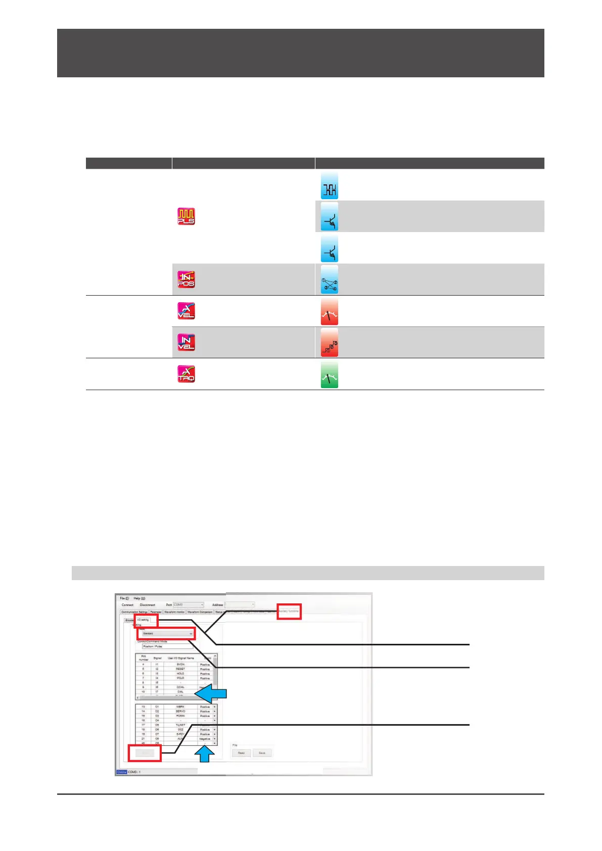
Changing the I/O conguration by Digitax SF Connect
1. Click I/O Setting under the Auxiliary Functions tab.
2. Select an I/O configuration type
Signal names of which assignments change due to your I/O preset
option change turn green.
3. Click Write.
Input/output logic polarity
It needs power cycling for the setting changes to take eect.