Parameter type Conditions for copy to non-volatile memory
User-save parameter
not visible in menu 0
Drive reset with 1000 in Parametermm.000 (mm.000) if the drive is not in the under voltage state and the standard under
voltage threshold is being used (i.e. LowUnderVoltageThresholdSelect (06.067) = 0).
OR
A drive reset with 1001 in Parametermm.000 (mm.000).
OR
After parameters are transferred from a non-volatile media card.
OR
After the drive mode is changed.
OR
After default parameters are loaded.
OR
After parameters are transferred from an electronic nameplate.
User save parameter
visible in menu 0
Under the conditions given above for user save parameters not visible in Menu 0.
OR
If the keypad is in edit mode for a user-save parameter in Menu 0, the parameter is saved when the keypad mode is
changed from edit mode.
Power-down save
parameter
A drive reset with 1000 in Parametermm.000 (mm.000) if the drive is not in the under voltage state and the standard under
voltage threshold is being used (i.e. LowUnderVoltageThresholdSelect (06.067) = 0).
OR
A drive reset with 1001 in Parametermm.000 (mm.000).
OR
On the transition into the under voltage state when the standard under voltage threshold is being used (i.e.
LowUnderVoltageThresholdSelect (06.067) is zero).
OR
After the drive mode is changed.
OR
After parameters are transferred from a non-volatile media card which results in the drive mode changing.
It can take some time for parameter data to be copied to non-volatile memory, especially if there are a large number of differences between the
parameter values in the drive and the values stored in the memory. Saving Power-down save parameters takes a maximum of 300ms, but saving user-
save parameters can take several seconds. If the drive is powered from a 24V control supply, or from a low voltage supply, the power down time of the
control system can be very short and there is a risk that either the stored values of the power-down save or user-save parameters could be corrupted.
This would result in an EEPROMFail trip at the next power-up. To reduce this risk, the power-down save and user-save parameters are each stored in
two banks. The banks are alternated each time a save is performed and the bank pointer is only updated once the save is complete. If the new bank is
corrupted a UserSave or PowerDownSave is initiated at the next power-up indicating an error in the user-save or power-down save data respectively,
and the data from the old bank is used. The following points should be noted:
1. If a UserSave or PowerDownSave trip occur at power-up then parameter changes made before power down will be lost. To clear these trips a
parameter save must be performed. If both the user-save and power-down save data is corrupted then a PowerDownSave trip is produced.
2. When a Menu 0 parameter is changed its value is saved immediately to the active bank and the bank pointer is not changed. Therefore
changes made via Menu 0 are not lost if a UserSave trip occurs at power-up.
3. When the drive mode changes all the data in both banks in the non-volatile memory is cleared and the default parameters are saved in both
banks. Therefore there is an extended parameter saving period immediately after a drive mode change.
4. Two banks are not provided in non-volatile media cards therefore the card could be corrupted if the power is removed when the drive is writing
data to the card.
Loading defaults
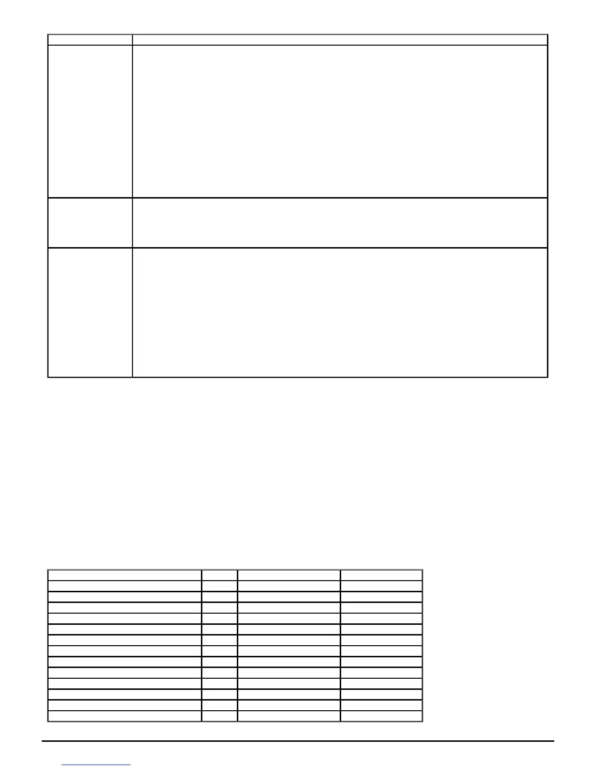
A drive reset with 1233 in Parametermm.000 (mm.000) loads the defaults defined for each parameter. If defaults are loaded with 1244 in Parameter
mm.000 (mm.000) then the parameters in the table below have different defaults that are intended for the 60Hz regions.
Parameter Default Drive modes Drive voltage rating
Maximumreferenceclamp (01.006) 60.0Hz Open-loop All
Maximumreferenceclamp (01.006) 1800rpm RFC-A All
StandardRampVoltage (02.008) 775V Open-loop, RFC-A, RFC-S 400V
RatedFrequency (05.006) 60.0Hz Open-loop, RFC-A All
RatedLoadrpm (05.008) 1800rpm Open-loop All
RatedLoadrpm (05.008) 1770rpm RFC-A All
RatedVoltage (05.009) 460V Open-loop, RFC-A, RFC-S 400V
M2MaximumReferenceClamp (21.001) 60.0Hz Open-loop All
M2MaximumReferenceClamp (21.001) 1800rpm RFC-A All
M2RatedFrequency (21.006) 60.0Hz Open-loop, RFC-A All
M2RatedLoadrpm (21.008) 1800rpm Open-loop All
M2RatedLoadrpm (21.008) 1770rpm RFC-A All
M2RatedVoltage (21.009) 460V Open-loop, RFC-A, RFC-S All
 Loading...
