Do you have a question about the Nieco JF94E and is the answer not in the manual?
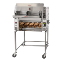
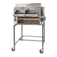
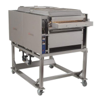
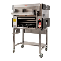
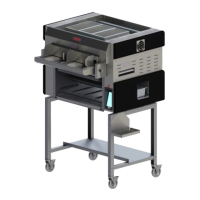
Overview of the Nieco Model JF94E automatic broiler's features and technology.
Details of the limited warranty coverage and exclusions for the broiler.
Contact information and procedures for obtaining service or technical support.
Critical safety warnings, symbols, and guidelines for safe operation.
Steps for uncrating, inspecting, and preparing the broiler for installation.
Guidelines for proper mounting, leveling, and required clearances around the broiler.
Instructions for connecting the broiler's electrical supply and pre-operation checks.
Explanation of controls and indicators on the main side of the broiler.
Explanation of controls and indicators on the flex side of the broiler.
Step-by-step procedures for lighting up and shutting down the broiler.
Detailed instructions for setting belt speeds and temperatures on the main side.
Instructions for operating multi-product control, belt speeds, and heat settings on the flex side.
Instructions on how to interpret cleaning section information and important symbols.
Steps for removing and cleaning the meat guide component.
Instructions for cleaning the feeder cover and feeder base parts.
Procedures for cleaning the feeder housing and front heat shield.
Steps for cleaning the grease pan and warming pan shield.
Instructions for cleaning lower heat reflectors and holding pan brackets.
Procedures for cleaning the product holding area and feed end grease trough.
Steps for cleaning the discharge heat shield and product slide.
Instructions for cleaning the stripper blade and chain shafts.
Procedures for cleaning the grease trough and grease box.
Steps for cleaning the Incendalyst catalyst and chimney.
Instructions for cleaning the upper air box reflector.
Procedures for cleaning the front and back air boxes.
Diagram showing the location of parts on the feed end of the broiler.
Diagram showing parts from the discharge, side, and top views.
Diagram identifying components within the right side control box.
Diagram identifying components within the left side control box.
Diagram identifying components within the motor control box.
Diagram showing the assembly and parts of the clutch mechanism.
Diagram illustrating the components of the feeder assembly.
Electrical schematic for the main side of the broiler.
Electrical schematic for the flex side of the broiler.
Electrical schematic for the motor control box.