EasyManuals Logo

Niles DBI-1 Installation Guide

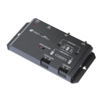
Niles DBI-1
11 pages
To Next Page IconTo Next Page
To Previous Page IconTo Previous Page
Page #6 background imageLoading...
Page #6 background image
INSTALLATION
CONSIDERATIONS
Included
mounting
wings
and
rubber
feet
provide
for
either
table
top
or
screw
down
mounting
(see
Figure
1
on
page
7).
The
included
UL-listed,
universal
voltage
power
supply
provides
power
to
the
DBI-1
(see
Figure
2
on
page
10).
The
DBI-1
connects
to
the
Paging
Input
of
a
Niles
Multi
Zone
Control
System
using
a
standard
audio
cable
with
male
RCA
connectors
(see
Figure
2
on
page
10).
A
paging
system
connects
to
the
Audio
Input
of
the
DBI-1
using
an
RCA
audio
cable
(see
Figure
2
on
page
10).
Doorbell
momentary
contact
closure
and
momentary
voltage
triggers
connect
to
the
DBI-1
using
two
conductor
wire
(see
Figure
2
on
page
10).
A
single
constant
Voltage
Trigger
Input
to
support
a
Lighted
Doorbell
Button.
(see
Figure
3
on
page
11).
INSTALLATION
MOUNTING
THE
DBI-1
Once
you
have
decided
on
the
location
for
the
DBI-1
(generally
near
the
location
of
the
Niles
MultiZone
Control
System),
make
sure
that
the
12V
DC
power
adapter
and
all
cables
are
disconnected
while
mounting.
The
DBI-1
can
be
either
mounted
on
the
back
of
a
cabinet
or
on
a
wall
using
screws
(not
included).
Also,
it
can
be
placed
on
a
shelf
using
the
included
adhesive
rubber
feet
(see
Figure
1
on
page
7).
CONNECTING
THE
DBM
1.
Connect
the
Audio
Output
of
the
DBI-1
to
the
Paging
Input
of
a
compatible
Niles
MultiZone
System
(see
Figure
2
on
page
10).
2.
(Optional)
Connect
the
Audio
Output
of
a
paging
system
to
the
Audio
Input
of
the
DBI-1
(see
Figure
2
on
page
10).
3.
Connect
the
voltage
and
or
contact
closure
trigger
cables
to
the
Chime
Triggers
(see
Figure
2
on
page
10).
4.
(a)
(Optional)
Connect
the
12V
DC
Voltage
Trigger
Output
to
a
voltage
activated
device.
(see
Figure
2
on
page
10).
(b)
Connect
the
12V
DC
Voltage
Trigger
Output
to
Door
number
one’s
(1)
Voltage
Trigger
Input
in
parallel
with
the
two
conductors
that
are
to
power
the
Lighted
Doorbell
Button.
5.
Connect
the
included
12V
DC
in-line
power
adapter’s
voltage
output
plug
into
the
DBI-1’s
power
jack
and
then
plug
its
AC
power
cord
into
an
unswitched
AC
outlet
(see
Figure
1
on
page
7).
The
red
LED
power
indicator
will
illuminate
to
confirm
proper
power
connection.
(CONTINUED
ON
NEXT
PAGE)
NILES
AUDIO
CORPORATION
-
1
800
BUY
HIFI
-
1-305-238
4373
-
9
8

Other manuals for Niles DBI-1

Questions and Answers:

Question and Answer IconNeed help?

Do you have a question about the Niles DBI-1 and is the answer not in the manual?

Niles DBI-1 Specifications

General IconGeneral
BrandNiles
ModelDBI-1
CategoryAccessories
LanguageEnglish

Related product manuals