D OORBELL I NTERFACE
7
D OORBELL I NTERFACE
6
OPERATION OVERVIEW
The DBI-1 is operated by the door bell switches and automation systems that connect to the
contact closure and voltage trigger inputs. Triggers for two individual chimes (Chime
Selection 1 & Chime Selection 2) are provided for a front and rear door.
INSTALLATION COSIDERATIONS
• Included mounting wings and rubber feet provide for either table top or screw down mount-
ing (see Figure 1 on page 5).
• The included UL-listed, universal voltage power supply provides power to the DBI-1
(see Figure 2 on pages 8-9).
• The DBI-1 connects to the Paging Input of a Niles MultiZone Control System using a stan-
dard audio cable with male RCA connectors (see Figure 2 on pages 8-9).
•A paging system connects to the Audio Input of the DBI-1 using an RCA audio cable
(see Figure 2 on pages 8-9).
• Doorbell momentary contact closure and momentary voltage triggers connect to the DBI-1
using two conductor wire (see Figure 2 on pages 8-9).
INSTALLATION
Mounting the DBI-1
Once you have decided on the location for the DBI-1 (generally near the location of the Niles
MultiZone Control System), make sure that the 12V DC power adapter and all cables are discon-
nected while mounting.
The DBI-1 can be either mounted on the back of a cabinet or on a wall using screws (not includ-
ed). Also, it can be placed on a shelf using the included adhesive rubber feet (see Figure 1 on
page 5).
Connecting the DBI-1
1. Connect the Audio Output of the DBI-1 to the Paging Input of a Niles MultiZone System
(see Figure 2 on pages 8-9).
2. (Optional) Connect the Audio Output of a paging system to the Audio Input of the DBI-1
(see Figure 2 on pages 8-9).
3. Connect the voltage and or contact closure trigger cables to the and Chime
Triggers (see Figure 2 on pages 8-9).
4. (Optional) Connect the 12V DC Voltage Trigger Output to a voltage activated device.
(see Figure 2 on pages 8-9).
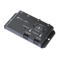
5. Connect the included 12V DC in-line power adapter’s voltage output plug into the DBI-1’s
power jack and then plug its AC power cord into an unswitched AC outlet (see Figure 1).
The red LED power indicator will illuminate to confirm proper power connection.