26
CALL 1-800-BUY-HIFI or 305-238-4373 – www.nilesaudio.com
ZR-6 MULTIZONE SYSTEM DESIGN GUIDE
Installation Bene ts
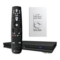
The VS-6 High Defi nition Component
Video Switcher is easily integrated with
the ZR-6 MultiZone Receiver. The VS-6 is
controlled by an R-8L or any learning
IR remote control.
Customer Bene ts
The ZR-6/VS-6 combination offers your
customer a cost-effective MultiZone
system that distributes both high defi nition
video and audio throughout the home. By
centralizing components into one area,
your customers eliminate “gear clutter” in
every room while gaining access to video
programming throughout their home with
a simple press of a button.
CRITICAL KNOWLEDGE
Always specify a secondary remote
control for all audio/video zones.
When installing the Solo-6IR or Solo-6MD
into a “wet” environment, the unit must
have a complete “positive” seal with the
mounting surface. This is achieved by
using silicone caulking on the gap around
the plate and the Decora
®
insert and then
installing the wall plate to complete the
seal. It is recommended that additional
installation time (and charges) be applied
to these keypad locations. It may be
necessary to disable the IR sensor if the
keypad is exposed to direct sunlight.
Whenever an iPod is connected to a
ZR-6, the Input 2 RCA jacks become an
iPod cascade output. These are used
to route the iPod audio signal to any
additional Slave chassis.
The ZR-6 can ONLY be used with the
SmartDock2 and ES2. Please check the
iWARE
®
2 iPod Compatibility Chart in the
Additional Documents section at:
www.nilesaudio.com/techsupport/
INSTALLATION REQUIREMENTS
All CAT-5 wiring must be terminated
using the T568 wiring convention. These
steps are required to confi gure a ZR-6 for
operation:
1. Set tuner presets
2. Confi gure unit through front panel
display
3. Teach IR codes into chassis
4. Create sequences for all Master keys
5. Set bass, treble, variable loudness, and
IR sensor on/off each zone from
keypad
6. Program all remotes (remotes must
be programmed with IR sequences to
control the ZR-6 and the local TV). The
ZR-6 controls the VS-6 automatically.
All connections on the VS-6 must
match the source inputs and zone
outputs on the ZR-6. Example: a DVD
connected to source 3 on the VS-6
would also connect to source 3 on the
ZR-6, and the zone 4 video output of
the VS-6 must match the zone 4 audio
output of the ZR-6.
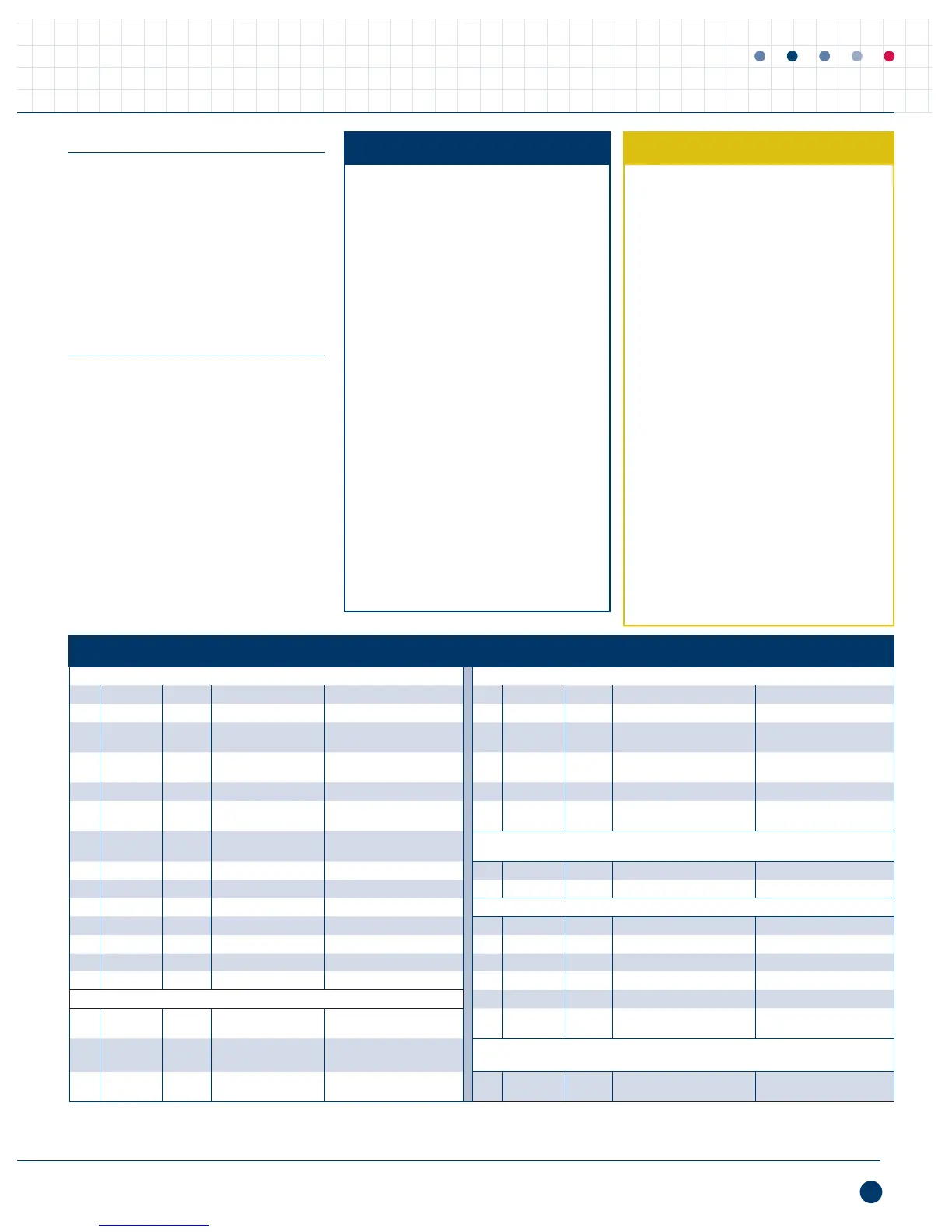
CABLE SCHEDULE
Source connections A/V Room connections (needed for each area that accesses the A/V sources)
QTY CABLE SIGNAL FROM TO QTY CABLE SIGNAL FROM TO
1
Stereo RCA Audio ZR-6 Source 2 Input AVDA-3
1
#1 Input 1 Speaker Audio ZR-6 Zone Amplifier Output Speakers
1
Stereo RCA Audio
Satellite Receiver
Audio Output
AVDA-3 #2 Input 1 CAT-5 Data ZR-6 Keypad Port
Keypad or
Touchscreen
1
Stereo RCA Audio
Cable Box
Audio Output
AVDA-3 #3 Input 1 CAT-5 Video VS-6 Zone Video Output C5-HDDAWM Balun
1
Stereo RCA Audio CD Audio Output AVDA-3 #4 Input 1 Component Video C5-HDDAWM Balun Video Out Television
1
Component Video
Satellite Receiver
Video Output
VS-6
2
Source #2 Input 1 CAT-5 Infrared IRH-610 Sensor Input MS220 IR Sensor
4
1
Component Video
Cable Box
Video Output
VS-6
2
Source #3 Input
Audio Room connections (needed for each area that accesses the audio sources)
1
Stereo RCA Audio AVDA-3 #1 Output Slave ZR-6 Source 2 Input 1 Speaker Audio ZR-6 Zone Amplifi er Output Speakers
1
Stereo RCA Audio AVDA-3 #2 Output Master ZR-6 Source 3 Input 1 CAT-5 Data ZR-6 Keypad Port Keypad or Touchscreen
1
Stereo RCA Audio AVDA-3 #2 Output Slave ZR-6 Source 3 Input
IR & ZR-6 Slave Control Connections
1
Stereo RCA Audio AVDA-3 #3 Output Master ZR-6 Source 4 Input 1 3.5mm Infrared IRH-610 Data Output Master ZR-6 Global IR Input
1
Stereo RCA Audio AVDA-3 #3 Output Slave ZR-6 Source 4 Input 1 Flasher Infrared Master ZR-6 Flasher #3 Satellite Receiver
1
Stereo RCA Audio AVDA-3 #4 Output Master ZR-6 Source 5 Input 1 Flasher Infrared Master ZR-6 Flasher #4 Cable Box
1
Stereo RCA Audio AVDA-3 #4 Output Slave ZR-6 Source 5 Input 1 Flasher Infrared Master ZR-6 Flasher #5 CD Player
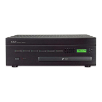
Systems Integration Amplifier Connections
1 3.5mm Infrared Master ZR-6 Flasher #6 VS-6 IR Input
1
Stereo RCA Audio
Slave ZR-6 Zone 6
Preamp Output
SI-275 Audio Input 1 CAT-5 Data Master ZR-6 Expansion Input Slave ZR-6 Expansion Output
1
3.5mm 12V DC
Slave ZR-6 Zone 6
12V DC Trigger Output
SI-275 Trigger Input
iPod Connection
1
Speaker Audio
SI-275
Speaker Output
Speakers
3
1
iPod
(supplied)
Audio +
Data
Master ZR-6 iPod Input iPod
1
Source 2 output is used to route iPod audio signal to slave ZR-6 chassis. This AVDA-3 is only required if a 2nd slave receiver is included.
2
The inputs used on the VS-6 must match the inputs used on the master ZR-6 chassis.
3
Up to 3 pairs of 8 ohm speakers can be connected to the SI-2125 amplifi er.
4
IR Sensor can be directly connected to the TS-Pro. IRH-610 is only required for IR Sensors in zones with Solo-6IR or Solo-6MD keypads.
 Loading...