C
carterkevinSep 9, 2025
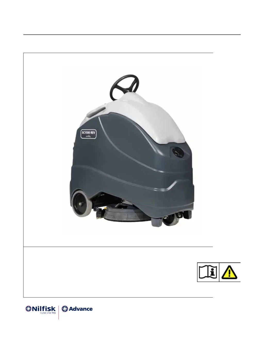
How do I troubleshoot an On-board Battery charger fault on a Nilfisk-Advance Scrubber?
- DDean BrooksSep 9, 2025
If the On-board Battery charger in your Nilfisk-Advance Scrubber has a fault, it may be due to an incorrect charging profile code or bit timing issues. Try resetting the charger or verifying the charging profile code.