Do you have a question about the Nilfisk-Advance Advance SC750 ST and is the answer not in the manual?
Explains the purpose and intended audience of the service manual.
Lists related manuals for Nilfisk and Advance models.
Defines directional terms used in the manual.
Provides safety instructions for transporting the machine.
Gives guidelines for safely towing the machine.
Explains safety symbols and warnings used in the manual.
Lists essential safety precautions for operating the machine.
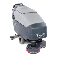
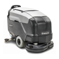
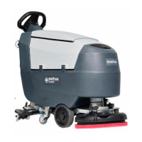
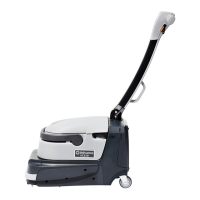
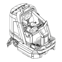
Provides a high-level overview of the machine's design and function.
Details the information found on the machine's identification plate.
Introduces the control panel and its components.
Lists technical specifications for SC750 and SC750 ST models.
Lists technical specifications for SC800 and SC800 ST models.
Outlines daily, weekly, monthly, and yearly maintenance tasks.
Explains the chassis's role in supporting machine components.
Describes the main and drive motor controllers and their functions.
Shows the physical placement of control system components.
Provides guidance for diagnosing and resolving control system issues.
Details procedures for removing and installing control system components.
Lists technical details related to the control system.
Overview of the machine's electrical power and protection systems.
Explains the functionality and installation of the optional on-board charger.
Identifies the physical locations of electrical system parts.
Covers maintenance procedures for batteries and charging.
Addresses issues related to insufficient operation time and charging.
Details battery removal and installation procedures.
Includes low voltage cut out thresholds and battery compartment dimensions.
Provides electrical schematics for SC750 and SC800 models.
Provides electrical schematics for ST models.
Shows the routing and connections of the wiring harness for SC750/SC800.
Shows wiring harness layout for ST models.
Describes a device indicating battery cell water level.
Explains a kit for easily adding water to all battery cells.
Describes the function of the hour meter.
Details the optional on-board charger.
Explains necessary wiring modifications for the charger.
Explains how the recovery system collects and stores dirty water.
Identifies the physical locations of recovery system parts.
Addresses issues with vacuum motor and water pickup.
Details vacuum motor removal and installation procedures.
Lists vacuum motor performance and amp draw specs.
Explains how the cylindrical scrub system operates.
Identifies components of the cylindrical scrub system.
Addresses issues with scrub motors and brush head movement.
Details scrub brush removal and installation.
Lists scrub motor amp draw, speed, force, and actuator specs.
Explains how the disc scrub system operates.
Identifies components of the disc scrub system.
Addresses issues with scrub motors and brush head movement.
Details brush head removal and installation.
Details how to replace scrub motor carbon brushes.
Covers removal and installation of the brush head actuator.
Lists scrub motor specs and gas spring force.
Explains how the solution system dispenses water and detergent.
Identifies the physical locations of solution system components.
Details the procedure for cleaning the solution filter.
Addresses issues with solution flow and leaks.
Covers removal and installation of the solution valve and tank.
Lists solution valve and pump winding resistance, and flow rate.
Explains how the squeegee collects and moves water.
Identifies components of the squeegee system.
Details how to adjust the squeegee tilt.
Addresses issues causing streaks on the floor.
Covers removal and installation of the squeegee tool.
Details removal and installation of the squeegee support.
Explains front and rear squeegee blade replacement.
Explains the function of the non-traction caster wheel.
Identifies the caster wheel location.
Describes the transaxle used for machine propulsion.
Details the drive motor circuit for ST models.
Explains how the drive motor controller outputs control speed and direction.
Details the drive motor circuit for non-ST models.
Explains how to power up the drive motor controller.
Describes inputs for paddle and speed control.
Identifies locations of drive system components.
Addresses issues with the drive system not propelling.
Covers removal and installation of the speed limit potentiometer.
Details removal and installation of palm button switches.
Details removal and installation of the reverse switch.
Covers removal and installation of the paddle position sensor.
Provides instructions for assembling paddle centering springs.
Details removal and installation of the drive wheel.
Covers removal and installation of the transaxle assembly.
Details replacing carbon brushes in the transaxle motor.
Lists drive wheel, motor, and potentiometer specifications.
| Brand | Nilfisk-Advance |
|---|---|
| Model | Advance SC750 ST |
| Category | Scrubber |
| Language | English |