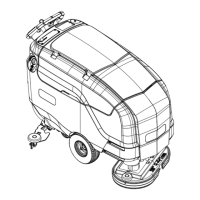
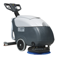
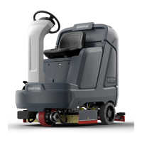
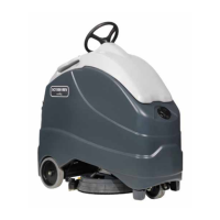
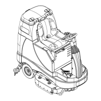
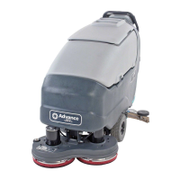
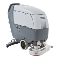
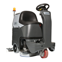
Service Manual: SC750, SC800, SC 750 ST, SC800 ST
Form Number 56043150 Page 121
Powering up the Drive Motor Controller:
This is the same as the “ST” models. See above secon.
Drive Motor Controller Inputs
To drive forward, the operator pushes on a drive paddle which rotates the Speed Control Potenometer inside the
paddle. A separate Speed Limit Potenometer is rotated to control the maximum speed.
The drive motor controller has internal “voltmeters” that are monitoring 2 inputs.
1. Drive Paddle Posion - To know when to move and which direcon.
2. Speed Limit - To know what the maximum speed should be.
The drive paddle Posion potenometer is fed 5 volts from the controller on one side of its resisve strip. The voltage
goes through the resisve strip and returns to baery negave inside the controller. The “wiper” inside the potenom-
eter will return a voltage back to the controller as a direcon request input. If the wiper is exactly in the middle, as it
should be when drive paddle is in the spring loaded posion, the return voltage will be ½ of the supply voltage (2.5v).
As the paddle is pushed forward, the wiper moves closer to the supply side, resulng in an increase in voltage. Volt-
age above 2.5v is interpreted as a forward request. The same input is also used for more or less speed. As the paddle is
pushed farther forward, the voltage will increase and it will be interpreted as a request for more speed in the forward di-
recon. (When the drive paddle is pulled back, the voltage will drop below 2.5v. and is interpreted as a reverse request).
The Speed Limit Potenometer is fed 5 volts from the controller on one side of its resisve strip. The voltage goes
through the resisve strip and returns to baery negave inside the controller. The “wiper” inside the potenometer will
return a voltage back to the controller as a speed request input. If the wiper is close to the supply side, the voltage will
be high (4.6v = Maximum speed request). If it is close to the baery negave return side, the voltage will be low (0.2v =
Minimum speed request).
The combinaon of the drive paddle posion potenometer input and the speed limit potenometer input allows the
operator to hold the paddle all the way forward for normal operaon while sll being able to adjust the travel speed.
Drive Motor Controller Outputs
• This is the same as the ST models. See secon above.

 Loading...

