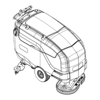
Service Manual: SC750, SC800, SC 750 ST, SC800 ST
Form Number 56043150 Page 77
Scrub System – Cylindrical
Functional Description
The scrub system moves the scrub head up and down and turns the scrub motors on and o at the operator’s request, to
provide oor scrubbing acon. The brushes spin toward one another at the boom. The head is moved up and down by
an electric actuator motor that has integrated posion switches. The weight of the scrub head provides the downward
pressure for scrubbing. The actuator linkage is sloed to allow the brush head to “oat” when going over low and high
spots on the oor. A spring is used to li just a bit of weight in order to obtain opmal scrub pressure weight. Note: The
cylindrical scrub system does not have an “extreme pressure” mode.
• The Main Machine Controller energizes the brush solenoid to turn on the brush motors when the following
inputs have been met:
o Key switch on
o Operator request
o Machine moving signal (FOR/REV)is received from the Drive Motor Controller (A2 PG Drives Speed Con-
troller)
Approximately 24 volts received from the main controller (J3 Pin 6) is switched to baery nega-
ve by the Drive Motor Controller, dropping the voltage to 0 volts.
Here is how the circuit works for the scrub motors: The Main Machine Controller turns on the scrub motors indirectly
by energizing the Brush Contactor. The brush contactor coil is fed baery posive voltage through the key switch. The
voltage goes through the coil and on to the controller. Inside the controller, it switches the circuit to baery negave to
energize the relay. When the relay energizes, posive baery voltage is applied through its contacts to the brush motors.
Since the other side of the motors is connected to baery negave, they turn on.
The Main Machine Controller also monitors the amount of electrical current (Amps) that is owing through the brush
motor ground circuit. If it is higher or lower than expected a fault code will be set. It monitors the amperage indirectly
on a “sense” wire by measuring the dierence in voltage (Voltage Drop) between a point near the motors and the main
baery negave terminal. As actual current increases, the voltage drop measured increases. The controller then converts
the voltage value to “Amps”. The monitoring circuit relies on a calibrated ground wire that is a specic gauge and length.
An electric actuator is used to move the scrub head up and down. The actuator has a DC permanent magnet electric mo-
tor which is driven by the Main Machine Controller. The motor turns a threaded sha. When the threaded sha turns, it
moves a threaded rod up and down. Since the rod is aached to the deck, it moves the deck up and down.
Inside the actuator housing, there are also three posion switches which are monitored by the Main Machine Controller.
One for the “retracted” posion, one for the “middle” posion (Normal scrub pressure) and one for the “Extended” posi-
on (Extreme scrub pressure). Each switch is normally closed. The threaded rod has a collar on it that opens each switch
as it passes by it. When the Main Machine Controller sees the middle posion switch open, it knows that the deck is in
the normal scrub posion. If that was its goal posion, the controller turns o the motor to stop the deck in that posi-
on.

 Loading...

