Service Manual: SC750, SC800, SC 750 ST, SC800 ST
Form Number 56043150 Page 44
Electrical System
Functional Description
General
The electrical system is powered by four 6 volt baeries for a total of 24 volts. Heavy cables connect the baeries in
series. A large red Main Baery Pack Connector provides baery power to the machine wiring. On machines without
an on-board baery charger, the Main Baery Pack Connector is used for hooking up the baeries to a “shelf” baery
charger unit. To prevent damage to the baeries due to excessive discharging, the control system will turn o the scrub
system and the recovery system as the baery voltage drops too low.
A steel plate at the back of the soluon tank serves as an “electrical panel” and provides a mounng surface for the vari-
ous relays, fuses and the Drive Motor Controller. Circuit breakers and a main fuse protect various circuits from excessive
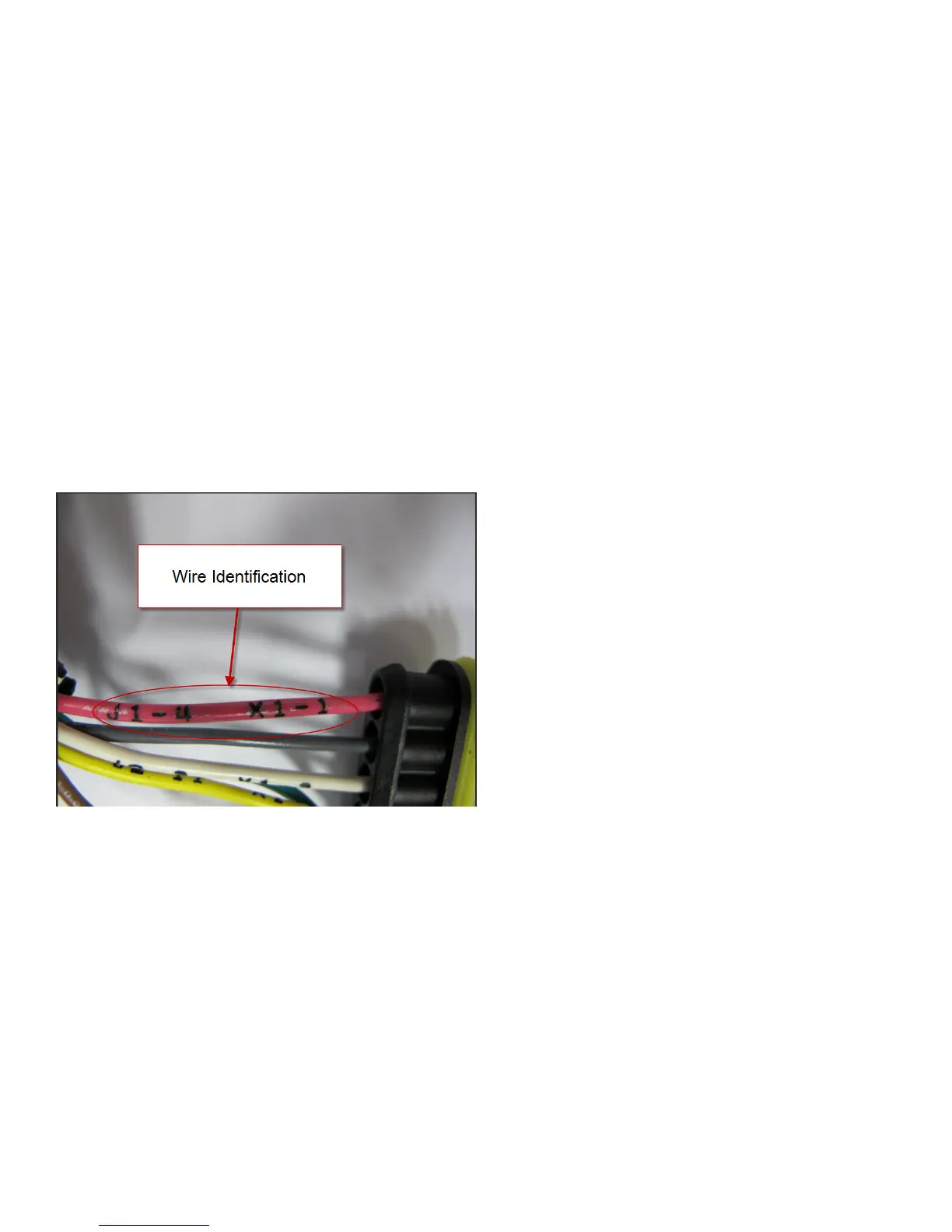
current. The machine wiring is color coded and the ends of each wire have the wire idencaon printed on them (such
as “J1-4 X1-1”). The wiring idencaon informaon can be used to more easily trace wiring in the machine because it is
also shown on the wiring harness conguraon diagram.
 Loading...